Animate Your Way to Glory - Part II
Math and Physics in Motion
Doctor… Who?
All the models we've dealt with until now are programmatic. If we wish to run a sequence of animations, we have to schedule calls appropriately, perhaps using a queue. The proper tool for this job is a timeline. At first glance, it's just a series of keyframes on tracks: a set of coordinates over time, one for each property you're animating, with some easing in between. But it's hard to offer direct controls to a director or animator, without creating uneven or jarring motion, at least in 2D.
We must stop treating space and time as separate things, and chart a course in both at the same time.
Timelines and splines are both sides of the same coin: using piecewise sections to create smoothness. The combination of both gives us path-based animation, pretty close to being the holy grail of controlled animation. We can fit this neatly into any timeline model—provided we don't lose track of all the tiny extra bits of time—with any easing mechanism we want. The track and the motion on it are completely decoupled.
Aside from Catmull-Rom, there's the non-rational splines, the popular Bezier curves as well as other recursive methods. As most of these allow you to control the slope directly, you get direct velocity control on any path in a timeline.
Path-based animations don't have to be restricted to positions either. You can animate RGB colors as XYZ triplets the same way. Or you could animate the parameters of a procedural generator, or a physics simulation. Or animate the volume levels of music in response to gameplay. Or move your robot. Timelines are excellent tools to manage change, but only if you can control the speed precisely at the same time.
Which leaves us only one thing: rotation.
Blowing up the Death Star
How difficult can a few angles be? Very. In 2D, they don't cooperate with our linear models. Even just turning to face a particular direction requires care. In 3D, things get properly messed up. Rotations will turn the wrong way, wobble in place and generally not behave. If you're trying to animate a free-moving camera in 3D, fixing this is pretty important, unless you're making Motion Sickness Tycoon or Cloverfield Returns.
Defeating this particular Goliath will require a careful approach. We'll launch our squadrons of X, Y and Z-wings, use the Force, and attack the weak spot for maximum damage. It better not be a trap.
What's wrong with angles? Let's ask our trusty friend, the apple. Sorry, I got hungry.
Well, they wrap around. Suppose we have an object that's been rotated a couple of times, for example as part of an interactive display. It completed 2.3 turns ($ τ = 2π $) around the circle. For now we'll use degrees, but eventually we'll switch to radians for the heavier stuff.
If we animate the apple to a target angle $ \class{purple}{\phi_T} $ at 0°, it will spin all the way back. Our animation system doesn't know that it could stop earlier at 720° or 360°.
To fix this, we can't simply reduce all angles to the interval 0…360. If we animate from 0 to 315°, we still go the long way around rather than just 45° in the other direction.
We need to reduce the difference in angle $ \class{purple}{\phi_T} - \class{blue}{\phi} $ to less than 180° in either direction. This is a circular difference, easiest when counting whole turns $ δ $, so we can round off to $├\,δ\,┤$. The difference, e.g. $ 3.3 - 3 = 0.3 $ or $ 1.6 - 2 = -0.4 $ is never more than half a turn. If we now set the target to 90°, it tells us to animate by $ \class{green}{+135°} $, that is, the short way around.
Our angles are now still continuous, going beyond 360° in either direction, but we never rotate more than 180° at a time unless we actually want to. We can apply this correction whenever we interpolate between two angles, and always end up at an equivalent angle.
Here I use double exponential easing to chase a rapidly changing angle. The once filtered angle jerks whenever it gets lapped, as it suddenly needs to change direction. The twice filtered angle moves smoothly however.
What about 3D? If we're restricting ourselves to a single axis of rotation, nothing really changes. We still control the angle the same way.
But orientation in 3D is a complicated thing. The easiest way to express it is with a 3×3 matrix: this is a set of 3 vectors in 3D. They define a frame of reference in space, a basis: right/left, up/down and forward/back. When we rotate around the vertical axis $ \vec y $, we rotate $ \vec x $ and $ \vec z $ together.
For arbitrary orientations, $ \vec x $, $ \vec y $ and $ \vec z $ can turn in any direction, but always maintain a perfect 90° angle between themselves.
Each vector is a set of $ (x, y, z) $ coordinates. That means we can write down the matrix as a set of 3 triples of coordinates, one column for each vector. At first it would seem we need 9 numbers to describe a 3D rotation. We can apply this rotation matrix to transform any point $ (x, y, z) $ by adding up proportional amounts of $ \vec x $, $ \vec y $ and $ \vec z $. This is linear algebra.
But there's tons of redundancy here. Because the 3 vectors are perpendicular, $ \vec z $ can only be in one of two places. The difference between the two is called a left handed or right handed coordinate system: for thumb, index and middle finger, with your hand shaped like a gun and the middle finger sticking out.
So long as we agree on a common style of coordinate system, for example right-handed, we don't need to track $ \vec z $. We can recover it from $ \vec x $ and $ \vec y $ using something called the vector cross product. The vector that comes out will always be perpendicular to the two we pass in, decided by a left- or right-hand rule. This is by the way how you can aim a camera in 3D: all you need is a target, and an up vector.
We're down to 6 numbers. But there's more. A rotation preserves length, so the basis must always stay the same size. All the vectors must have length 1—be normalized—and hence move on the surface of a sphere.
Instead of 3 coordinates, we can remember $ \vec x $ as two angles: longitude $ \phi $ and latitude $ \theta $. First we rotate around the Y axis, then around the rotated Z axis. Did we uniquely determine $ \vec y $ as well?
No, there is a third degree of freedom we haven't been using so far. In order to account for all the places where $ \vec y $ can be, we need to allow rotation around $ \vec x $, by another angle $ \gamma $. Now we can describe any orientation in 3D using just three numbers, the so called Euler angles.
This is a YZX gyroscope, after the order of rotations used. We can build one in real life by using concentric rings connected by axles. Make one large enough to put a chair in the middle, and you've got an amusement ride—or something to train pilots with. When we rotate the object inside, we rotate the rings, decomposing the rotation into 3 separate perpendicular ones.
If we animate the individual angles smoothly, like here, we seem to get a smooth orientation. What's the problem? Well, we need to study the gyroscope a bit more.
Let's go back to neutral, setting all angles to 0. You can see the YZX nature of the gyroscope, if you follow the axles from the outside in.
We rotate the first ring by 90° and look at the axles again. Now they go YXZ. We've swapped the last two.
If we rotate the second ring by 90°, the axles change again. They've moved to YXY. This means changing the order or nature of the axles doesn't change the gyroscope, it just rotates all or part of it. That is, unless you make the very useless YYY gyroscope. All functional gyroscopes are identical. Whatever we discover for one applies to all.
This configuration is special however. The axles for the first and third rings are aligned. This is called gimbal lock, though no ring actually locks. If we apply an equal-but-opposite rotation to both, the apple doesn't move. From any of these configurations, we can only rotate two ways, not three. It shows Euler angles do not divide rotations equally.
If we now rotate the inner ring by 90°, all rings have been changed 90° from their initial position. Same for the apple: its final orientation happens to be rotated -90° around the Z axis.
Which means if we rotate the entire gyroscope by 90° around Z, the apple returns to its original orientation. This is what we'd like to see if we simultaneously rotated the three rings of the gyroscope back to zero.
That's not the case however. We try to hold the apple in place, by rotating back the gyroscope as we rotate back all three rings at the same time. The rotations don't cancel out cleanly and the apple wobbles. We'll need to create an angle map, similar to the distance map for splines before. Only now we need to equalize three numbers at the same time.
Another telling sign is when we rotate all rings by 180°: the start and end orientation is the same. Yet the apple performs a complicated pirouette in between. Just like with circular easing, we'll need a way to identify equivalent orientations and rotate to the nearest one.
To see why this is happening, we can rotate the apple around a diagonal axis. You can do this with a real gyroscope just by turning the object in the middle. The three rings—and hence the Euler angles—undergo a complicated dance. The two outer rings wobble back and forth rather than completing a full turn. Charting a straight course through rotation space is not obvious.
In summary: trying to decompose rotations is messy and leads to gimbal lock. We're going to build a different model altogether, using what we just learnt.
First, we make an arbitrary rotation matrix by doing a random X rotation followed by a (local) Y rotation and a (local) Z rotation. This is like using an XYZ gyroscope.
We can apply the same rotations again, acting like a nested XYZXYZ gyroscope. Because the gyroscope is made of two equal parts in series, we've rotated twice as far.
Three points uniquely define a circle. So we can trace an arc for each of the basis vectors. These arcs are not part of the same circle, but they do lie parallel to each other. They turn around a common axis of rotation.
We can find this common axis from any of the arcs. We take the cross product of the forward differences. If we divide by the lengths of the differences, the cross product's length tells us about the angle of rotation. We apply an arcsine to get an angle in radians. This is the axis-angle representation of rotations. Note that the axis is oriented to distinguish clockwise from counter-clockwise, here using the right hand rule.
We can do this for any rotation matrix, for any set of Euler angles. It tells us we can rotate from neutral to any orientation by doing a single rotation around a specific axis. Now we have three better numbers to describe orientations: $ \class{purple}{(x, y, z)} $. They don't privilege any particular rotation axis, as both their direction and length can change equally in all 3 dimensions. We can pre-apply the arcsine: we make the vector's length directly equal rotation angle, linearizing it.
We can also identify equivalent angles: if we rotate more than 180° one way, that's equivalent to rotating less than 180° the other way. The axis can flip around when its length reaches $ π $ radians (180°) without any disruption. We can restrict axis-angle to a ball of radius $ π $.
If we interpolate linearly to a different $ \class{purple}{(x, y, z)} $, we get a smooth animation, but there's some wobble. It also goes the long way through the sphere. There's a much shorter way.
We can flip $ \class{purple}{(x, y, z)} $ and then interpolate back, to get a more direct rotation. The wobble remains though: there's a subtle change in direction at the start and end. Hence, axis-angle cannot be used directly to rotate between any two orientations in a single smooth motion.
If we have two random rotation matrices $ [\class{blue}{\vec x_1} \,\,\, \class{green}{\vec y_1} \,\,\, \class{orangered}{\vec z_1}] $ and $ [\class{slate}{\vec x_2} \,\,\, \class{cyan}{\vec y_2} \,\,\, \class{purple}{\vec z_2}] $, how can we find the axis-angle rotation that turns one directly onto the other?
We have to invert the first matrix to turn the other way. We could convert it to axis-angle and then reverse the angle. But it turns out that's the same as swapping rows and columns. The latter is obviously a lot less work, but it only works because the three vectors are perpendicular and have length 1. We end up with a matrix that rotates the same amount around the same axis, but in the other direction. For other kinds of matrices, inversion is trickier.
To apply the inverted rotation, we do a matrix-matrix multiplication, which is a fancy way of saying we use it to rotate the other matrix's basis vectors $ [\class{slate}{\vec x_2} \,\,\, \class{cyan}{\vec y_2} \,\,\, \class{purple}{\vec z_2}] $ individually. When applied to the first basis $ [\class{blue}{\vec x_1} \,\,\, \class{green}{\vec y_1} \,\,\, \class{orangered}{\vec z_1}] $, it rotates back to neutral as expected, aligned with the XYZ axes.
We can now convert the relative rotation matrix into axis-angle again. This is the rotation straight from A to B, without any wobble or variable speed. This method is quite involved, and hence is still just a stepping stone towards rotational bliss.
We go back to our axis-angle sphere and apply this rotation, while measuring the total axis-angle every step along the way. We can see the cause of the earlier wobble: when moving straight through rotation space, we need to follow a curved arc rather than a straight line. As both rotations are the same length, this arc follows the surface of the sphere.
To get a better feel for how this works, let's move the other end around. We change it to various rotations of $ \frac{π}{2} $ radians (90°). These are all the rotations on a sphere of radius $ \frac{π}{2} $. Both the arc and axis of rotation change in mysterious ways. The arc snaps back and forth, crossing through the edge of the sphere if that's shorter.
What this really means is that angle space itself is curved. Think of the surface of the earth: if we keep going long enough in any particular direction, we always get back to where we started. As a consequence, you can't flatten an orange peel without tearing it, and you can't make a flat map of the Earth without distorting the shapes and area unequally. Yet we can view such a curved 2D space easily in 3D: it's just the surface of a sphere.
The same applies here, except not just on the surface, but also inside it. Each curved arc is actually straight as far as rotation is concerned, and each straight interpolation is actually curved. The inside of this ball is curved 3D space.
If we want to see curved 3D space without distorting it, we need to view it in four dimensions. This ball is the hypersurface of a 4D hypersphere. So 3D rotation is four dimensional. WTF?
Math is boring. Let's blow up the Death Star.
 The Emperor has made a critical error and the time for our attack has come. The data brought to us by the Bothan spies pinpoints the exact location of the Emperor's new battle station. We also know that the weapon systems of this Death Star are not yet operational. Many Bothans died to bring us this information. Admiral Ackbar, please.
 Although the weapon systems on this Death Star are not yet operational, the Death Star does have a strong defense mechanism. It is protected by an energy shield, which is generated from the nearby forest Moon of Endor. Once the shield is down, our cruisers will create a perimeter, while the fighters fly into the superstructure and attempt to knock out the main reactor.
 Sir, I'm getting a report from Endor! A pack of rabid teddy bears has attacked the generator, tearing the equipment to shreds. The shield is failing…
The Death Star is completely vulnerable! Report to your ships, we launch immediately. We'll relay your orders on the way.
Lieutenant Hamilton, show me the interior of the superstructure.
(That's your cue.)
*Mic screech*
Red Wing, these are your orders. Of the 6 access points to the interior, you will fly your X-wings through the east portal, closest to the superlaser.
There are large passageways leading directly to the central chamber. As these shafts are heavily guarded by fighters, a direct assault is impossible. We will need to avoid patrols by navigating the dense tunnel network that makes up the interior.
The Death Star's inner core is fortified, and all access is restricted. However, one of our operatives has informed us of a large, unsecured ventilation shaft, still under construction. This is our best chance to get into the core and destroy it. You must reach this target at all costs.
Tip: Click and drag to see things from a different angle.
There are large tunnels circling just underneath the surface. You will fly your fighters into: (Choose one)
We will also send a detachment of Y-wings from the north pole. These heavy bombers will rendezvous with the X-wings, taking the long way around, away from the defensive perimeter.
Lieutenant, I have another task for you. Now that the Death Star's shields have conveniently failed, we will launch a probe ahead of our arrival, gathering detailed sensor data of the entire structure.
It will approach directly from the front side. It must pass through each of the large tunnels circling the Death Star to ensure full sensor coverage.
The probe's energy signal is shielded, but it will not escape detection for long. To minimize our chances of detection, we should complete the survey of the entire Death Star without any overlap.
Survey all areas of the Death Star, without entering any tunnel twice.
The probe is approaching the Death Star…
Scan of the interior progressing. Plotting data now.
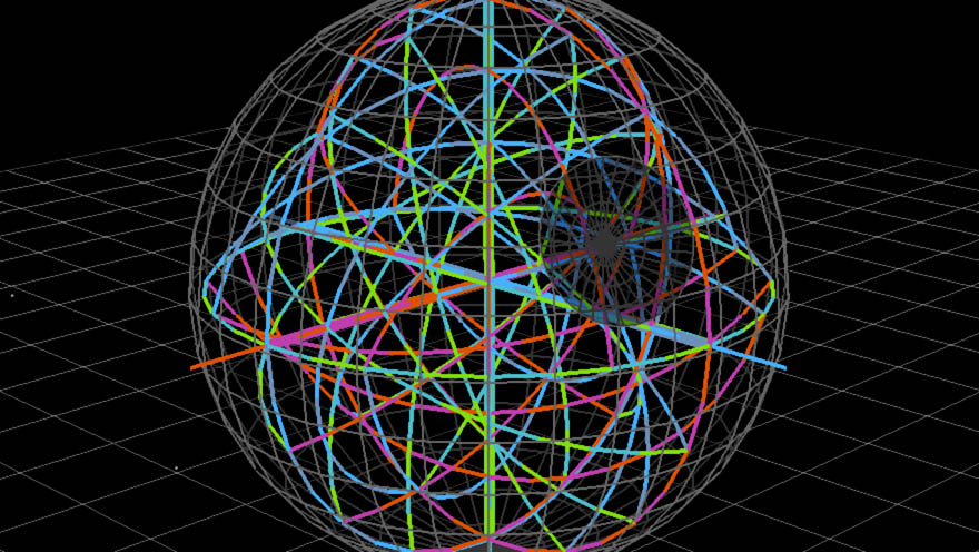
Hamilton's head hurts. Who would design such a crazy, tangled thing? Yet as he studies the structure, he notices a remarkable symmetry. Grouped by color, the tunnels form a swirling vortex around each central axis. Each vortex is surrounded by a great circle. He labels the three groups $ i $, $ j $ and $ k $, as is the convention in this era.
Yet mysteriously, tunnels always meet at a 90° angle, everywhere: on the central axes, on the circles, even anywhere in between. The colors also maintain their relative orientation at each intersection, including the polarity (positive or negative). Amazed, Hamilton starts scribbling down notes. "Cubic grid, twisted through itself? $ i → j → k $?".
In fact, he's so mesmerized by the display, he's completely lost track of what's going on. As the hustle and bustle of the starship bridge slowly creeps back into focus, he looks up and–…
IT'S A TRAP!
Not to despair. Some lightning gets thrown around, the Emperor is killed, a man finds redemption in death, and the Death Star is destroyed.
That night, after many hours of celebration, the young Lieutenant falls asleep contentedly, and starts dreaming of that maze again. Maybe it was just a flash of inspiration, maybe it was the Force—or maybe the interesting neurochemical effects of fermented Endorian moonberry juice—but a long time ago, in a galaxy far, far away, William Rowan Hamilton figured out quaternions.
More precisely, it was in 1843 in Dublin, Ireland. He was so struck by it, he immediately carved it into the nearest bridge—true story. It shouldn't surprise you that you've been doing quaternion calculations all along: those edges weren't color-coded just to look pretty. They consistently denoted the multiplication by a +X/-X, +Y/-Y or +Z/-Z quaternion, representing a particular rotation around that axis.
A key feature is how the colors wrap around the great circles. They always maintain the same relative orientation at every intersection, but the entire arrangement rotates from one place to the next. For example +Y: it goes up at the core, but circles around the equator horizontally. You also saw what the inside looked like, omitted here for sanity.
But we're missing something: a 6th quaternion at every 'pole'. This space continues outward, we've just been ignoring that part of it.
This suggests there is a second set of 'poles', at twice the radius. We can travel to and from them by multiplying with a quaternion. In fact that's completely true, but with one catch: all the orange points are actually all one and the same point. Huh?
Remember, we're looking at curved space, a hypersphere. To make sense of it, we need to first look at the 2D case.
If the disc represents a curved plane that was projected down to 2D, then in its undistorted form, it's actually a sphere. All the points on the disc's perimeter are actually the same: here they're the north pole, and the disc's center is the south pole.
In curved space, it works similar. We can't visualize this, because this is happening in every direction all at the same time. We experienced the result of it while navigating the Death Star. What we didn't see was that the entire sphere of radius 2π—in axis-angle terms—is all just one and the same point. We never bothered to go beyond radius π before: rotations up to 180° in either direction.
The important thing is to realize that the center of our diagram is not the center of the hypersphere, rather it's just another pole. In order to fit a hypersphere into 3D correctly, we'd somehow have to shrink the entire sphere of radius 2π to a point, to create a new pole, but without passing through the sphere of radius π. This is impossible, you need an extra dimension to make it work.
But why are 3D rotations and quaternions connected? Why does axis angle map so cleanly to half of a hypersphere in quaternion space? And what does a quaternion actually look like? Well. What other kind of mathematical thing likes to turn? When you multiply it by another one of its kind? Where the rotation angle depends on where both inputs are?
Complex numbers! Yay! If you're not familiar with them however, not to worry. We won't be needing all the complex numbers: we'll only use those that have length 1. In other words, all points on a circle of radius 1. Much simpler.
Complex numbers are 2D vectors that lead a double life. Ordinarily, they are written as the sum of two parts. Their horizontal component is a real number, a multiple of $ \class{royal}{1} $. Their vertical component, is a so-called imaginary number, a multiple of $ \class{blue}{i} $, which is a square root of -1. Which supposedly does not exist. Lies.
It is often better to see them as a length and an angle. $ \class{royal}{1} $ becomes $ \class{royal}{1∠0°} $. The number $ \class{blue}{i} $ becomes $ \class{blue}{1∠90°} $. And $ -1 $ becomes $ 1∠180° $ or $ 1∠-180° $.
When we multiply two complex numbers, their lengths multiply, and their angles add up. As the lengths are always 1 in our case, we can ignore them. Here, we multiply $ \class{orange}{1∠30°} $ by $ \class{blue}{1∠90°} $ to turn it 90° counter-clockwise. By the same rule, $ \class{blue}{1∠90°} \cdot \class{blue}{1∠90°} = 1∠180° $, better known as $ \class{blue}{i}^2 = -1 $. Complex numbers like to turn, and this gives them interesting properties, explored elsewhere on this site.
Representing 2D rotation with complex numbers is trivial. We can directly map the rotation angle to the complex number's angle, and we can combine rotations by adding up the angles, positive or negative. The angles 0°, 90°, 180°, 270°, 360° become 1, $ \class{blue}{i} $, -1, $ -\class{blue}{i} $, 1. Of course, this adds nothing useful, at least in 2D.
We can expand the model to 3D though, where we have three perpendicular ways of turning. First we'll try to add a second degree of rotation. We add a new imaginary component $ \class{green}{j} $, representing Y rotation, while $ \class{blue}{i} $ is X rotation. Any position in this 3D space is now a quaternion, but we're still limiting them to only length 1, only interested in rotation. We'll be using the surface of what is, for now, a sphere.
But wait, this isn't right. According to this diagram, if we rotate 180° around either the X or Y axis, we end up in the same place—and hence the same orientation. Clearly that's not the case. Yet we based our quaternions on complex numbers, so both $ \class{blue}{i}^2 = -1 $ and $ \class{green}{j}^2 = -1 $.
We can satisfy this condition in a different way though. If we rotate an object by 360° around any axis, we always end up back where we started. So we can make this rule work if we agree that a 360° rotation equals a 180° quaternion.
That means each rotation is represented by a quaternion of half its angle. A rotation by 180° becomes a quaternion of 90°, that is $ \class{blue}{i} $ or $ \class{green}{j} $, and each rotation axis takes us to a unique place. As we still treat $ \class{royal}{1} $ as 0°, the quaternion $ \class{blue}{1∠180°} = \class{green}{1∠180°} = -1 $ now represents a rotation of 360° = 0° around any axis. So $ \class{royal}{1} $ and $ -1 $ are considered equivalent, as far as representing rotation goes.
Furthermore, $ \class{blue}{i} $ and $ \class{slate}{-i} $ are equivalent too, and so are $ \class{green}{j} $ and $ \class{cyan}{-j} $. Each represents rotating either +180° or -180° around the corresponding axis, which is the same thing. In fact, any half of this sphere is now equivalent to the other half, when you reflect it around the central point. This is why we were missing half of the hypersphere earlier: the 'outer half' is a mirror image of the 'interior'.
So what about in-between axes? Well, we could try rotating around $ \class{orange}{(1,1,0)} $ and $ \class{gold}{(1,-1,0)} $, which are the axes that lie ±45° rotated between X and Y. We'd end up tracing circles right between them: this is the only possibility where both rotations are perpendicular, yet maintain an equal distance to both the X and Y situation.
Unfortunately we're missing something important. We've only applied rotations from neutral, from $ 1 $. If we apply a 180° X and Y rotation in series, where do we end up? And what about Y followed by X? The diagram might suggest we'd end up at respectively $ \class{green}{j} $ and $ \class{blue}{i} $.
But this wouldn't make sense: if $ \class{blue}{i} \cdot \class{green}{j} = \class{green}{j} $, and $ \class{green}{j} \cdot \class{blue}{i} = \class{blue}{i} $, then both $ \class{blue}{i} $ and $ \class{green}{j} $ have to be equal to $ 1 $. There'd be no rotation at all. And if we say that $ \class{blue}{i} \cdot \class{blue}{j} = \class{blue}{j} \cdot \class{blue}{i} = -1 $, then the quaternions $ \class{blue}{i} $ and $ \class{green}{j} $ have the exact same effect. We'd only have one imaginary dimension, not two. Even in math, a difference that makes no difference is no difference.
Whether we want to or not, we have to add a third imaginary component, $ \class{orangered}{k} $ to make this click together. So $ \class{orangered}{k}^2 = - 1 $, but it's different from both $ \class{blue}{i} $ and $ \class{green}{j} $. As we've used up our 3 dimensions, we need to project down this new 4th, putting it at an angle between the others. Again, a $ \class{orangered}{k} $ quaternion represents rotation around the Z axis, with the angle divided by two.
We end up with two peculiar relationships: $ \class{blue}{i} \cdot \class{green}{j} = \class{orangered}{k} $ and $ \class{green}{j} \cdot \class{blue}{i} = \class{purple}{-k} $. The quaternion product is not the same when you reverse the factors. Just like an XY gyroscope turns differently than a YX gyroscope. But if we'd started with Z/X or Y/Z, we'd see the exact same thing.
Hence we can rotate and combine these rules to get $ \class{blue}{i} \cdot \class{green}{j} \cdot \class{orangered}{k} = -1 $. This is the $ i^2 = -1 $ of quaternions, the magic rule that links together 3 separate imaginary dimensions and a real one, creating a maze of twisty passages all alike. When you cycle the axes, it still works: $ \class{green}{j} \cdot \class{orangered}{k} \cdot \class{blue}{i} = -1 $ and $ \class{orangered}{k} \cdot \class{blue}{i} \cdot \class{green}{j} = -1 $, demonstrating that quaternions link together three imaginary axes into a cyclic whole.
So how do we actually use quaternions for rotation? It's quite easy, because they are literally complex numbers whose imaginary component has sprouted two extra dimensions. Compare with an ordinary complex number on the unit circle. Its length (1) is divided non-linearly over the horizontal and vertical component using the cosine and sine: this is trigonometry 101.
For a quaternion on the unit hypersphere, we only make two minor changes. We replace the single $ i $ with a vector $ (x\class{blue}{i}, y\class{green}{j}, z\class{red}{k}) $ where $(x,y,z)$ is the normalized axis of rotation. The cosine and sine stay, though we divide the rotation angle by two. We can visualize the 3 imaginary dimensions directly without projection, after squishing the real dimension to nothing. As the length of the imaginary vector shrinks, the real component grows to compensate, maintaining length 1 for the entire 4D quaternion.
We can apply the rules of quaternion arithmetic to multiply two quaternions. This is equivalent to performing the rotations they represent in series. Just like complex numbers, two length 1 quaternions make another length 1 quaternion. Of course, all the other quaternions have their uses too, but they're not as common. In a graphics context, you can pretty much forget they exist.
There's only one question left: how to smoothly move between two quaternions, that is, between two arbitrary orientations. With axis-angle, it was a very complicated procedure. With quaternions, it's super easy, because unit quaternions are shaped like a hypersphere. The 'angle map' is the hypersphere itself.
As it turns out though, a hyperspherical interpolation in 4D is exactly the same as a spherical one in 3D. So we really only need to understand the 3D case. We have a linear interpolation between two points on a sphere, and want to replace it with a spherical arc.
The line and the arc share the same plane: the one that contains both points and the center of the sphere. Any such plane cuts the sphere into two equal halves, along an equator-sized great circle. Hence the arc is just an inflated version of the line, with a circular bulge applied in the plane, following the sphere's radius along the way. But we also have to traverse the arc at constant speed: otherwise we'd end up creating an uneven spline-like curve again.
Luckily, we can apply a little trigonometry again. We can use the 3D (4D) vector dot product to find the angle between two unit vectors (quaternions), after applying an arccosine. Then we weigh the two vectors (quaternions) appropriately so they sum to length 1 and move linearly with the arc length. This is the slerp, the spherical linear interpolation. Working it out yourself can be tricky, but the result is elegant and independent of the number of dimensions.
With all that in place, we can track any orientation with just 4 numbers, and change them linearly and smoothly. Quaternions are like a better axis-angle representation, which simply does the right thing all the time. Of course, you could just look up the formulas and cargo-cult your way through this problem. But it's more fun when you know what's actually going on in there. Even if it's in 4D.
So that's quaternions, the magical rotation vectors. Every serious 3D engine supports them, and if you've played any sort of 3D game within the last 15 years, you were most likely controlling a quaternion camera. Whether it's head-tracking on an Oculus Rift, or the attitude control of a spacecraft (a real one), these problems become much simpler when we give up our silly three dimensional notions and accept 3D rotation as the four dimensional curly beast that it is.
Ultimately though, quaternions can be treated as just vectors with a special difference and interpolation operator. We can apply all our usual linear filtering tricks, and can create sophisticated motions on the hypersphere. Combine that with smooth path-based animation with controllable velocities, and you have everything you need to build carefully tracked shots from any angle.
Meaning from Motion
It's useful to see where we actually are with animation tools, especially on the web. Unfortunately, it doesn't look that great. For most, animation means calling an .animate() method or defining a transition in CSS with a generic easing curve, fire-and-forget style. Keyframe animation is restricted to clunky CSS Animations, where we only get a single cubic bezier curve to control motion. We can't bounce, can't use real friction, can't set velocities or apply forces. We can't blend animations or use feedback. By now you know how ridiculously limiting this is.
In an ideal world, we'd have a perfect animation framework with all the goodies, which runs natively and handles all the math for us while still giving direct control. Until then, consider inserting a little bit of custom animation magic from time to time. Writing a simple animation loop is easy, and offers you fine grained control. Upgrades can be added later when the need presents itself. Your audience might not notice directly, but you can be sure they will remark on how pleasant it is to use, when everything seems alive.
But buyer beware: we need to be thinking as much about what isn't changing, as what is. Just like we use grids and alignment to keep layouts tidy, so should we use animation consistently to bring a rhythm and voice to our interactions.
In what you just saw, little was left to chance. Color, size, proportion, direction, orientation, speed, timing… they're used consistently throughout, there to reinforce the connections that are expressed. I try to hash ideas into memorable qualia, while avoiding optical illusions or accidental resemblances. If it's not the same, it should look, act or speak differently. Even if it's just a slightly different shade of blue, or a 300ms difference in timing.
Though MathBox is a simple script-based animator (for now), it exposes some interesting knobs to play with and can handle arbitrary motion through custom expressions. It also supports slowable time and maintains per-slide clocks. If you map bullet time to a remote control, you can manipulate time mid-sentence: you don't need to follow your slides, your slides follow you. It feels ridiculously empowering when you're doing it. When properly applied, you can build up a huge amount of context and carry it along for extended periods of time at the forefront of people's attention.
Many of these slides are based on live systems that run in the background, advancing at their own pace. The entire diagram reflows, maintaining the mathematical laws and relations that are represented. Often, I use periodic or pseudo-random motion to animate the source data. While it may just seem like a cool trick at first, I think it's actually the main feature. It changes every slide from one example into many different ones. It shows them one after the other, streaming into your brain at 60 frames per second. It maximizes the use of visual bandwidth, yet cause and effect can still be read directly from any freeze frame.
Additionally, looping creates a continuous reinforcement of the depicted mechanisms. In my experience, our intuition can absorb math this way through mere exposure, slowly internalizing models of abstract spaces, as well as the relations and algorithms that operate within. Even if we don't notice right away, it anchors our understanding for later when it's finally expressed formally and verbally.
That's the theory anyway: put the murder weapon on the mantelpiece in the opening scene, and work your way towards revealing it. Only the weapon could be complex exponentials, and the mantelpiece the real number line. I'm not an education specialist or neuroscientist, though I did devour David Marr's seminal work on the human visual system. I just know that whenever I manage to pour a complicated concept into a concise and correct visual representation, it instantly begins to make more sense.
Bret Victor has talked about media as thinking tools, about needing a better way to examine and build dynamical systems, a new medium for thinking the unthinkable. In that context, MathBox is an attempt at viewing the unviewable. To borrow a term, it's qualiscopic. It's about creating graphical representations that obey certain laws, and in doing so, making abstract things tangible. It encourages you to smoothly explore the space of all possible diagrams, and find paths that are meaningful.
By carefully crafting living dioramas of space and time this way, we can honestly say: nothing will appear, change or disappear without explanation.
Comments, feedback and corrections are welcome on Google Plus. Diagrams powered by MathBox.