Making Worlds 1 - Of Spheres and Cubes
Let's start making some planets! Now, while this started as a random idea kind of project, it was clear from the start that I'd actually need to do a lot of homework for this. Before I could get anywhere, I needed to define exactly what I was aiming for.
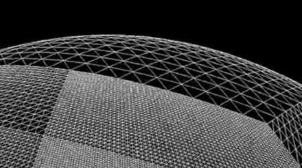
The first step in this was to shop around for some inspirational art and reference pictures. While there is plenty space art to be found online, in this case, nothing can substitute for the real thing. So I focused my search on real pictures, both of landscapes (terran or otherwise) as well as from space. I found classy shots like these:
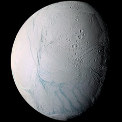

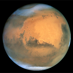
Hopefully I'll be able to render something similar in a while. At the same time, I eagerly devoured any paper I could find on rendering techniques from the past decade, some intended for real-time rendering, some old enough to be real-time today. Out of all this, I quickly settled on my goals:
- Represent spherical or lumpy heavenly bodies from asteroids to suns.
- With realistic looking topography and features.
- Viewable across all scales from surface to space.
- At flight-simulator levels of detail.
- Rendered with convincing atmosphere, water, clouds, haze.
For most of these points, I found one or more papers describing a useful technique I could use or adapt. At the same time, there are still plenty of unknowns I'll need to figure out along the way, not to mention significant amounts of fudging and experimentation.
The Spherical Grid
To get started I needed to build some geometry, and to do that I needed to figure out what geometry I should use. After reviewing some options, I quickly settled on a regular spherical displacement map (AKA a heightmap). That is, starting with a smooth sphere, move every surface point up or down, perpendicular to the surface, to create terrain on the surface.
If these vertical displacements are very small compared to the sphere radius, this can represent the surface of a typical planet (like Earth) at the levels of detail I'm looking for. If the displacements are of the same order as the sphere radius, you can deform it into very irregular potato-like shapes. The only thing heightmaps can't do is caves, tunnels, overhang and other kinds of holes, which is fine for now.
The big question is, how should the spherical surface be divided up and represented? With a sphere, this is not an easy question, because there is no single obvious way to divide a spherical surface into regular sections or grids. Various techniques exist, each with their own benefits and specific use cases, and I spent quite some time looking into them. Here's a comparison between four different tesselations:
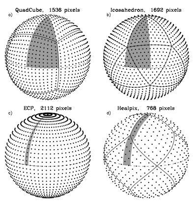
Note that the tesselation labeled ECP is just the regular geographic latitude-longitude grid.
The main features I was looking for were speed and simplicity, so I settled on the 'quadcube'. This is where you start with a cube whose faces have been divided into regular grids, and project every surface point out from the middle to an enclosing sphere. This results in a perfectly smooth sphere, built out of 6 identical round shells with curved edges. This arrangement is better known as the 'cube map' and often used for storing arbitrary 360 degree panorama views.
Here's a cube and its spherical projection:
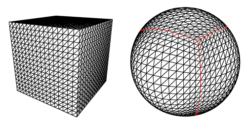 The projected cube edges are indicated in red. Note that the resulting sphere is perfectly smooth and round, even though the grid has a bulgy appearance.
Cube maps are great, because they are very easy to calculate and do not require complicated trigonometry. In reverse, mapping arbitrary spherical points back onto the cube is even simpler and in fact natively supported by GPUs as a texture mapping feature.
This is important, because I'll be generating the surface terrain and texture dynamically and will need to index and access each surface 'pixel' efficiently. Using a cube map, I simply identify the corresponding face, and then index it using x/y coordinates on the face's grid.
The downside of cube maps is that the distance and area between points varies along the grid, which makes it harder to perform certain operations on a surface equally. However, these area distortions are much smaller than e.g. a lat-long grid, where the grid spacing actually approaches zero near the poles. Even more, the distortions made by a cube map are the exact opposite of those you get with a regular perspective projection. This makes it easy to render into cube maps, which will be useful for texture generation.
Level of Detail
There's another reason I picked the cube map approach, and that has to do with the level of detail requirements. My goal is to make a planet that can be viewed from the ground, the air as well as from space. It would be incredibly slow to always render everything at maximum detail, so I need to adaptively add and remove detail as the viewer gets closer to the surface.
However, increasing the level of detail uniformly across the entire sphere is not enough, because I only want to render detail where the viewer will see it. To a viewer on the ground, most of the planet is hidden by the horizon, and the engine should be able to effectively cut away the unseen pieces, so no wasteful processing takes place.
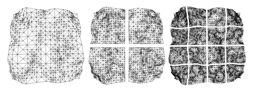
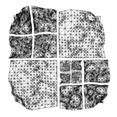
It is here that I get a huge benefit from the cube map layout of the sphere, because it lets me apply the well-researched realm of grid-based flat terrain rendering with only minor adjustments. Specifically, I am using a 'chunked LOD' approach. Every face of the cube map becomes a quadtree, with each level splitting four ways to form the next level with more detail:
The chunks for the various levels of detail are all loaded into GPU memory, ready to be accessed at any time. When the terrain has to be rendered, the engine walks down the quad-tree, determines the appropriate level-of-detail for each section, and outputs the list of chunks to be rendered for a particular frame. Then, the GPU does its work, blasting through each chunk at a blistering pace, leaving the CPU to do other things.
Because all the data is already in memory, changing the level of detail just means rendering a different set of chunks. Each chunk has the same geometrical complexity, and performance is directly proportional to how many are rendered on screen. More detail means more chunks, but that usually also means you can cut away pieces of the terrain that are far away.
The chunked approach is also very easy to work with, because there is no data dependency between the different chunks. Each chunk has a copy of its own vertex data, which means individual chunks can be paged in and out of GPU memory at will. This is important for keeping memory usage down while still being able to scale to massive sizes.
Putting It All Together
At this point, I have all the pieces in place to render an adaptive sphere mesh. This is what it looks like (sorry, the video capture is a bit jerky):
The detail increases as the camera gets closer to the sphere and shifts around the surface as it moves.
Far from being a little coding experiment, it actually took me quite some time to get to this point, because I was learning OGRE, sharpening my C++ skills, as well as researching the techniques to use.
The next step is to look at generating heightmaps and textures for the surface.
References
The techniques I used were pioneered by people smarter and older than me, I'm just building my own little digital machine with them.
- Creating Spherical Worlds, Maxis/Electronic Arts. (source).
- Rendering Massive Terrains using Chunked Level of Detail Control, Thatcher Ulrich. (source)