On Evitability in Use of AI

If the hype is to be believed, software development as we know it is over. Strangely though, despite now years of LLM-powered tooling, the results look, feel and function mostly the same as they ever did: barely.
It's undeniable there's a metric gigaton of hype surrounding the technology. It drives the enormous amounts of money and infrastructure being poured into it, which in turn demands more hype to justify the investment. The history of hyperbole is already evident, as new models continue to be trained to reach promises which now-retired models were already supposed to deliver.
So allow me to drop a line that would shock a weathered San Franciscan more than open defecation on Market Street: it's perfectly okay not to use AI.
It doesn't make you a troglodyte. It won't leave you choking behind in the dust as self-fashioned techno-wizards bring their agents to bear. In fact, it seems far less stressful and far more satisfying than the alternative.
Craft vs Kraft
In all the talk of what it is that LLMs do and don't, there are a lot of ways to frame what is happening. The positive spin includes helpfulness, cleverness, creativity and productivity. The negative spin points at lazyness, disposability, theft, and decay of knowledge. But there's one word that's remarkably absent in the discourse. That word is forgery.
- If someone produces a painting in the style of Van Gogh, and passes it off as being made by Van Gogh, by putting his signature on it, that painting is a forgery.
- If someone produces a legal document by mimicking the format, impersonating the parties, and faking their agreement, that document is a forgery.
- If someone produces a study by inventing or altering data, making up citations, and cherry-picking results to fit a particular conclusion, that study is a forgery.
Whether something is a forgery is innate in the object and the methods used to produce it. It doesn't matter if nobody else ever sees the forged painting, or if it only hangs in a private home. It's a forgery because it's not authentic.
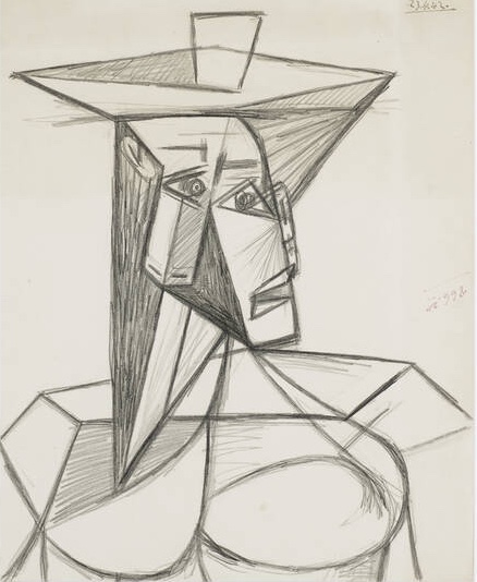
P. Picasso, "Buste De Femme" – 1942
In this perspective, LLMs do something very specific: they allow individuals to make forgeries of their own potential output, or that of someone else, faster than they could make it themselves.
The act of forgery is the act of imitation. This by itself is strictly-speaking legal, as a form of fiction or self-expression. It's only when one attempts to use a forgery as a substitute for the authentic thing that it creates problems. How this plays out in practice depends on the situation, and mainly depends on what authenticity would signify.
That is, nobody will be arrested for "forging" a letter from Santa Claus, but also, no jurisdiction would allow you to have extremely convincing "imitation money" purely as a collector's item.
This sort of protectionism is also seen in e.g. controlled-appelation foods like artisanal cheese or cured ham. These require not just traditional manufacturing methods and high-quality ingredients from farm to table, but also a specific geographic origin. There's a good reason for this.
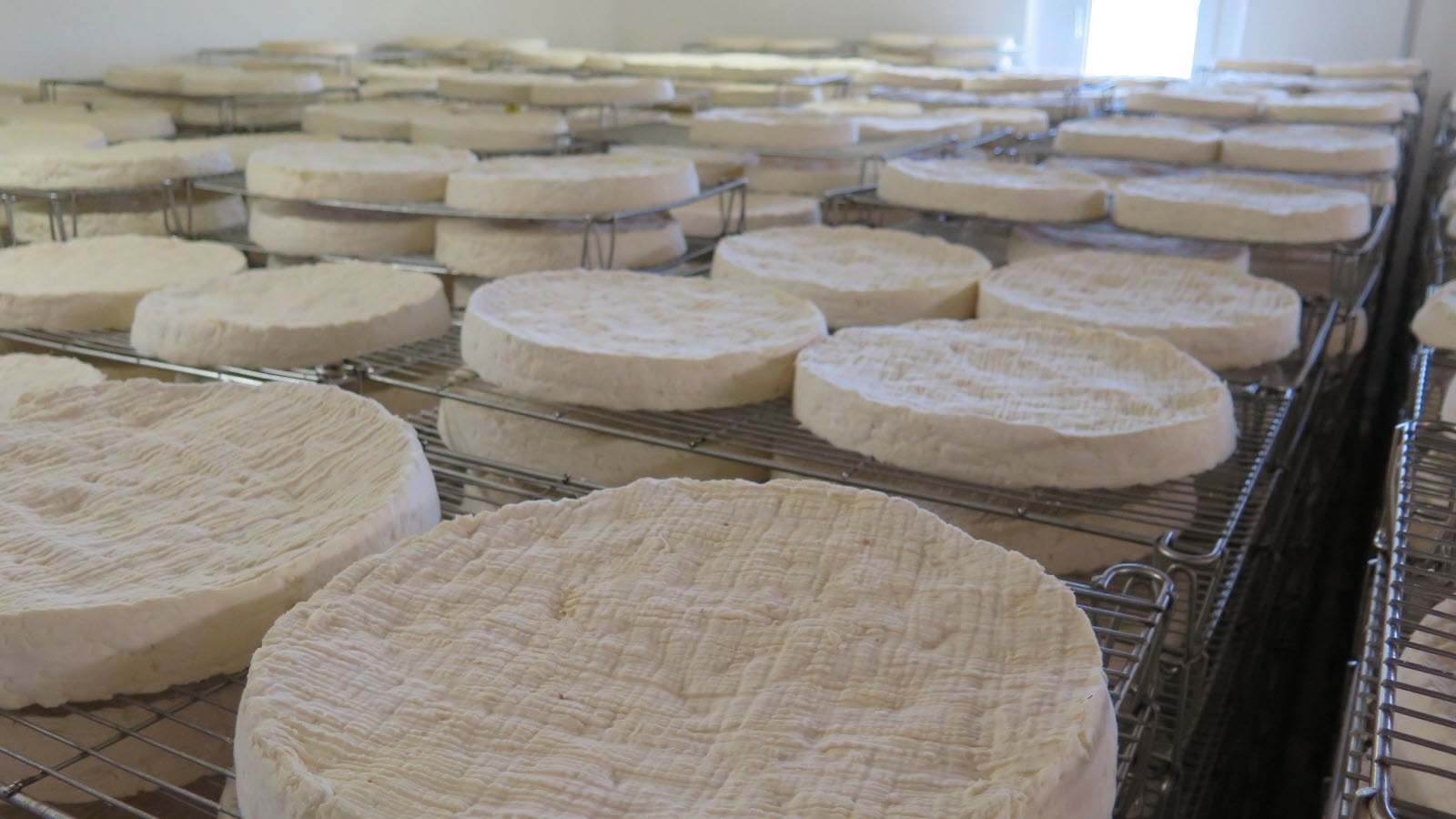
Producing French "Brie de Meaux" abroad isn't allowed, because it would open the floodgates to inevitable cheaper imitations. This would degrade the brand of the authentic product, and threaten the rare local expertise necessary to produce it, passed down from generation to generation.
The judgement of an individual end-consumer simply isn't sufficient here to ensure proper market function. The range of products that you can get in the store, between which you can choose, has already been pre-decided by factors out of your control. The quality of the artisanal cheese is a stand-in for an entire supply chain, often run on modern methods, which cannot simply be transplanted elsewhere without enormous investments in human capital, infrastructure and agriculture. This isn't mere romanticism.
Every society has to draw a line somewhere on the spectrum between "traditional artisanal cheese" and "fake eggs made from industrial chemicals", if they don't want people to die from malnutrition or poisoning. But it's the ones that understand and maintain the value of foodcraft that don't end up with 70%+ obesity rates.

Distrust and Verify
The parallels to LLM-driven software coding are not difficult to find. The craft of writing software is being threatened by a literal flood of cheap imitations.
Open source software maintainers have been one of the first to feel the downsides. They already had a ton of difficulty finding motivated contributors and bringing them up to speed on the project's goals and engineering mindset. The last thing they needed was to receive slop-coded pull requests from contributors merely looking to cheat their way into having a credible GitHub resumé.


Being on the receiving end of this is both demeaning and absurd, as the only thing the vibe-coder can do with the feedback you give them is paste it back into the tool that produced the errors in the first place.
As a result, projects have closed down public contributions and dropped their bug bounties. Others just mock the posers and hope they go away. What this certainly isn't is helpful, clever, creative or productive.
In day to day coding, working alongside vibe-coding co-workers has similar effects. While new employees might seem to get up to speed much quicker, in reality they're merely offloading those arduous first weeks to a bot, hoping no-one else notices.
In the process, they'll inject run-of-the-mill mediocrity all over the place, when what you were really hoping for was their specific perspective. Anno 2026, if a new employee produces an extremely detailed PR with lots of explanation and comments, doubt every word.
Experienced veterans who turn to AI are said to supposedly fare better, producing 10x or even 100x the lines of code from before. When I hear this, I wonder what sort of senior software engineer still doesn't understand that every line of code they run and depend on is a liability.
One of the most remarkable things I've heard someone say was that AI coding is a great application of the technology because everything an agent needs to know is explained in the codebase. This is catastrophically wrong and absurd, because if it were true, there would be no actual coding work to do.
It's also a huge tell. The salient difference here is whether an engineer has mostly spent their career solving problems created by other software, or solving problems people already had before there was any software at all. Only the latter will teach you to think about the constraints a problem actually has, and the needs of the users who solve it, which are always far messier than a novice would think.
When software is seen as an end in itself, you end up with a massively over-engineered infrastructure cloud, when it could instead be running on a $10/month VPS, with plenty of money left for both backups and beer.
Tools for Tools
Engineers who know their craft can still smell the slop from miles away when reviewing it, despite the "advances" made. It comes in the form of overly repetitive code, unnecessary complexity, and a reluctance to really refactor anything at all, even when it's clearly stale and overdue.
I've also observed several times now that even being senior, with years of familiarity, will not save them from vibe-coding some highly embarrassing goofs, and passing them on like an unpleasant fart.
Trying to imagine what thought-process produced the odd work in question will quickly lead to the answer: none at all. It's not a co-pilot, it's just on auto-pilot.
The same applies to vibe-coders themselves, and the reactions are largely predictable. The notion is being felt that slop code is bad code, full of bugs, with e.g. Microsoft's Co-pilot Discord recently banning the insult "Microslop". The user backlash was then framed as "spam" and even outright "harmful", demonstrating that the promise is often worth more than the actual result, and also, that the universe still has a sense of humor.

Less encouraging is that you'll see these tools referred to as "addicting" or even "the best friend you can have". While nerds being utterly drawn to computers is as old as the PC revolution itself, there doesn't seem to be an associated cambrian explosion of creativity and accomplishment to go with it.
I can understand why outsiders would be impressed by it, what I don't understand is how so many insiders didn't stop and think about it.

What gets built with AI is really all the glue that's become necessary since said PC revolution, as software applications have gotten more closed, more distributed and more corporate. The options here for end-users are terrible. HTTP APIs don't make things open if every endpoint requires a barely documented JSON blob whose schema changes overnight. Slinging raw database dumps is also not viable, and is only used for disaster recovery. Software has largely rusted shut.
Consider that many companies still primarily run on Excel. What's the Excel of JSON? There is none. So yeah, of course users think they need a machine to translate their intent into code so they can run it. Even then, what's the Jupyter notebooks of JSON?
There's jq of course, but keep in mind that originally it was SQL that was framed as the solution that was going to free businesses and their workers from having to rely on dedicated tools. Look how that worked out... the more things change, the more they stay the same. Is there a standard CRDT-like protocol for syncing editable graphs yet?
Surprisingly, we haven't seen a return to native apps either. It turns out vibe-coding an Electron app is still preferable to vibe-coding on multiple platforms and delivering a tailored experience for each. So where is this famed 100x? If even Apple can't maintain proper form and iconography in their latest OS anymore, what chance does an AI trained on web-slop have?
It says a lot about our industry, it just doesn't say much about engineering at all.

And a Bottle of Rum
Software engineers have largely jumped in without a life-jacket, but not every industry has been as eager. The frame of inevitability is just that, a frame, and one which you should question.
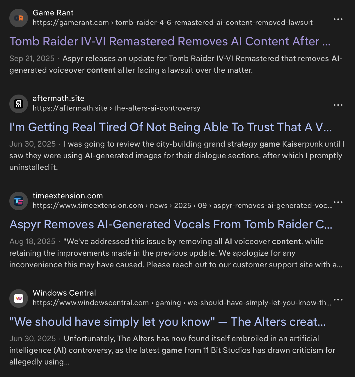
Video games stand out as one market where consumers have pushed back effectively. Numerous titles have already apologized for unlabeled AI content and removed it. Platforms like Steam have clearly signposted policies about it, and tools exist to filter it out.
That said, Steam's policy has been recently updated to exclude dev tools used for "efficiency gains", but which are not used to generate content presented to players.
This isn't all that surprising, for two reasons.
The first is that video games are a pure direct-to-consumer market with digital delivery. Gamers really do have all the choices on tap. When they don't like a game or its pricing model, it's the result of choices made by those specific producers. Other titles exist without those flaws, and those get promoted and bought instead. The taste-makers are gamers themselves, who demand transparency.
But the second is that most video games are artistic, and bought for their specific artistic appeal. In art, copy-catting is frowned upon, as it devalues the original and steals the credit. Artists are rationally very sensitive to this, as part of the appeal of art is a creator's unique vision. The art is supposed to function as a personal proof-of-work, whose integrity must be preserved. The proper form of imitation is instead an homage, which respects and evolves an idea at the same time.
This stands in stark contrast to code, which generally doesn't suffer from re-use at all, or may even benefit from it, if it's infrastructure. It also explains why open source projects are so particularly ill-suited to attracting talented, artistic creatives. The ethos of zero-cost sharing means any artistic design would be instantly pilfered and repurposed without its original context.
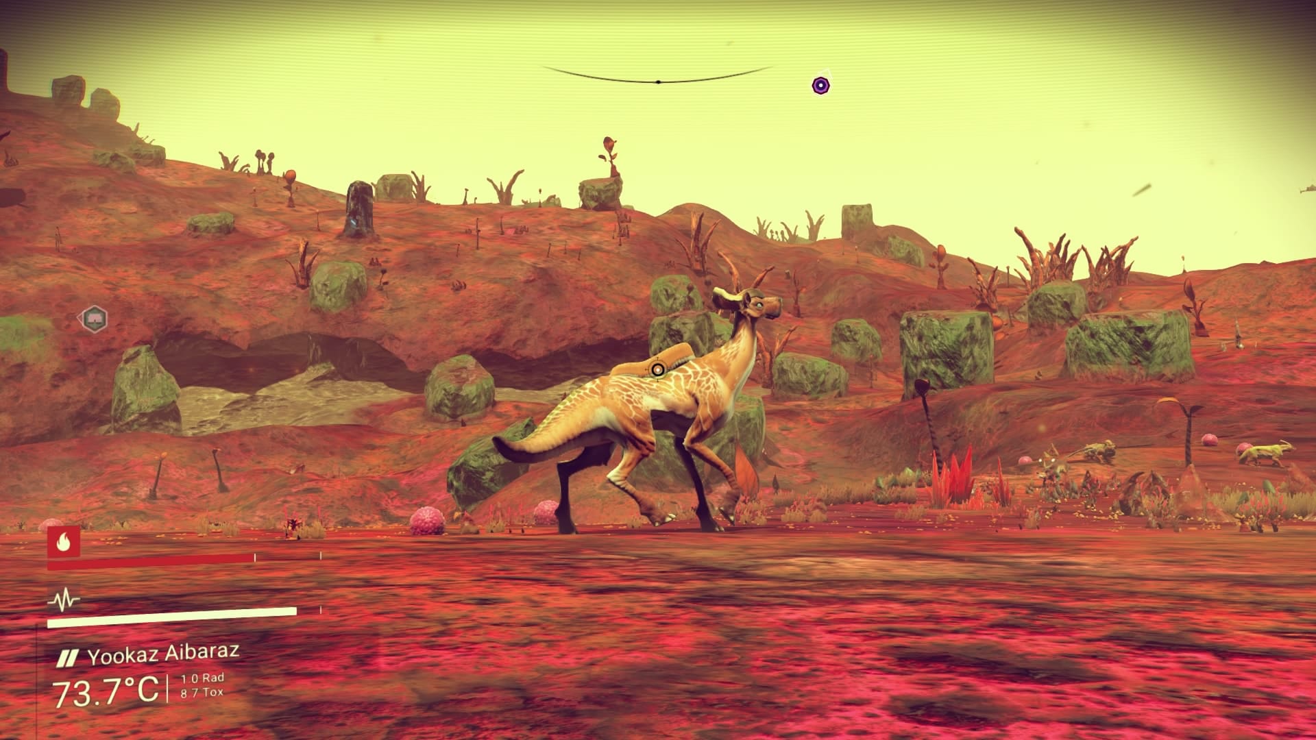
Classic procedural generation is noteworthy here as a precedent, which gamers were already familiar with, because by and large it has failed to deliver. The promise of exponential content from a limited source quickly turns sour, as the main thing a procedural generator does is make the variety in its own outputs worthless.
So it's no wonder artists would denounce generative AI as mass-plagiarism when it showed up. It's also no wonder that a bunch of tech entrepreneurs and data janitors wouldn't understand this at all, and would in fact embrace the plagiarism wholesale, training their models on every pirated shadow library they can get. Or indeed, every code repository out there.
If the output of this is generic, gross and suspicious, there's a very obvious reason for it. The different training samples in the source material are themselves just slop for the machine. Whatever makes the weights go brrr during training.
This just so happens to create the plausible deniability that makes it impossible to say what's a citation, what's a hallucination, and what, if anything, could be considered novel or creative. This is what keeps those shadow libraries illegal, but ChatGPT "legal".
Labeling AI content as AI generated, or watermarking it, is thus largely an exercise in ass-covering, and not in any way responsible disclosure.
It's also what provides the fig leaf that allows many a developer to knock-off for early lunch and early dinner every day, while keeping the meter running, without ever questioning whether the intellectual property clauses in their contract still mean anything at all.
This leaves the engineers in question in an awkward spot however. In order for vibe-coding to be acceptable and justifiable, they have to consider their own output disposable, highly uncreative, and not worthy of credit.
* * *
If you ask me, no court should have ever rendered a judgement on whether AI output as a category is legal or copyrightable, because none of it is sourced. The judgement simply cannot be made, and AI output should be treated like a forgery unless and until proven otherwise.
The solution to the LLM conundrum is then as obvious as it is elusive: the only way to separate the gold from the slop is for LLMs to perform correct source attribution along with inference.
This wouldn't just help with the artistic side of things. It would also reveal how much vibe code is merely just copy/pasted from an existing codebase, while conveniently omitting the original author, license and link.
With today's models, real attribution is a technical impossibility. The fact that an LLM can even mention and cite sources at all is an emergent property of the data that's been ingested, and the prompt being completed. It can only do so when appropriate according to the current position in the text.
There's no reason to think that this is generalizable, rather, it is far more likely that LLMs are merely good at citing things that are frequently and correctly cited. It's citation role-play.
The implications of sourcing-as-a-requirement are vast. What does backpropagation even look like if the weights have to be attributable, and the forward pass auditable? You won't be able to fit that in an int4, that's for sure.
Nevertheless, I think this would be quite revealing, as this is what "AI detection tools" are really trying to solve for backwards. It's crazy that the next big thing after the World Wide Web, and the Google-scale search engine to make use of it, was a technology that cannot tell you where the information comes from, by design. It's... sloppy.
To stop the machines from lying, they have to cite their sources properly. And spoiler, so do the AI companies.


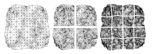


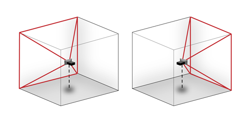 Rendering two different cube map faces. The red area is the camera's viewing cone/pyramid, which extends out to infinity.

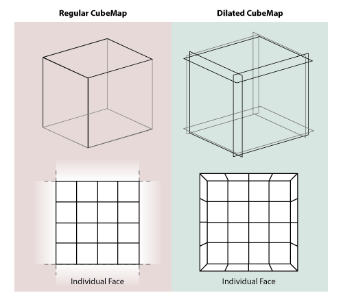


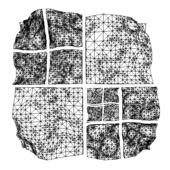
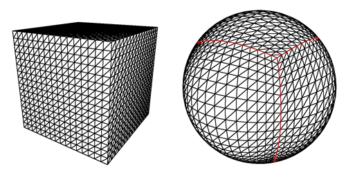 The projected cube edges are indicated in red. Note that the resulting sphere is perfectly smooth and round, even though the grid has a bulgy appearance.
