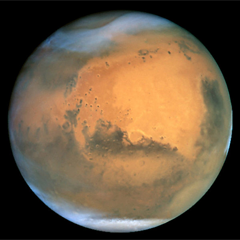
Last time I'd reached a pretty neat milestone: being able to render a somewhat realistic rocky surface from space. The next step is to add more detail, so it still looks good up close.
Adding detail is, at its core, quite straightforward. I need to increase the resolution of the surface textures, and further subdivide the geometry. Unfortunately I can't just crank both up, because the resulting data is too big to fit in graphics memory. Getting around this will require several changes.
Strategy
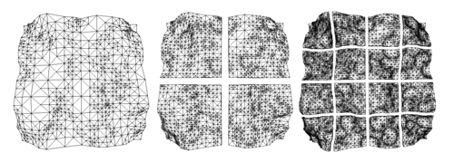
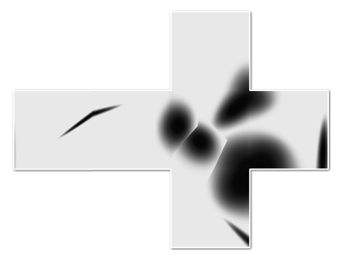
Until now, the level-of-detail selection code has only been there to decide which portions of the planet should be drawn on screen. But the geometry and textures to choose from are all prepared up front, at various scales, before the first frame is started. The surface is generated as one high-res planet-wide map, using typical cube map rendering:

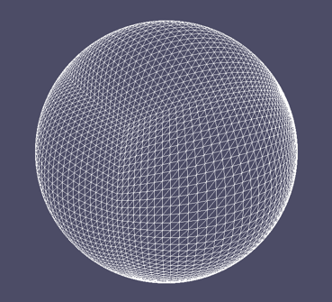
This map is then divided into a quad-tree structure of surface tiles. It allows me to adaptively draw the surface at several pre-defined levels of detail, in chunks of various sizes.
This strategy won't suffice, because each new level of detail doubles the work up-front, resulting in exponentially increasing time and memory cost. Instead, I need to write an adaptive system to generate and represent the surface on the fly. This process is driven by the Level-of-Detail algorithm deciding if it needs more detail in a certain area. Unlike before, it will no longer be able to make snap decisions and instant transitions between pre-loaded data: it will need to wait several frames before higher detail data is available.
Uncontrolled growth of increasingly detailed tiles is not acceptable either: I only wish to maintain tiles useful for rendering views from the current camera position. So if a specific detailed portion of the planet is no longer being used—because the camera has moved away from it—it will be discarded to make room for other data.
Generating Individual Tiles
The first step is to be able to generate small portions of the surface on demand. Thankfully, I don't need to change all that much. Until now, I've been generating the cube map one cube face at a time, using a virtual camera at the middle of the cube. To generate only a portion of the surface, I have to narrow the virtual camera's viewing cone and skew it towards a specific point, like so:

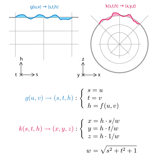
This is easy using a mathematical trick called homogeneous coordinates, which are commonly used in 3D engines. This turns 2D and 3D vectors into respectively 3D and 4D. Through this dimensional redundancy, we can then represent most geometrical transforms as a 4x4 matrix multiplication. This covers all transforms that translate, scale, rotate, shear and project, in any combination. The right sequence (i.e. multiplication) of transforms will map regular 3D space onto the skewed camera viewing cone.
Given the usual centered-axis projection matrix, the off-axis projection matrix is found by multiplying with a scale and translate matrix in so-called "screen space", i.e. at the very end. The thing with homogeneous coordinates is that it seems like absolute crazy talk until you get it. I can only recommend you read a good introduction to the concept.
With this in place, I can generate a zoomed height map tile anywhere on the surface. As long as the underlying brushes are detailed enough, I get arbitrarily detailed height textures for the surface. The normal map requires a bit more work however.
Normals and Edges
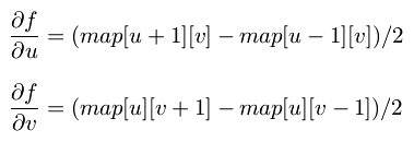
As I described in my last entry, normals are generated by comparing neighbouring samples in the height map. At the edges of the height map texture, there are no neighbouring samples to use. This wasn't an issue before, because the height map was a seamless planet-wide cube map, and samples were fetched automatically from adjacent cube faces. In an adaptive system however, the map resolution varies across the surface, and there's no guarantee that those neighbouring tiles will be available at the desired resolution.
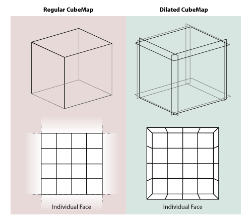
The easy way out is to make sure the process of generating any single tile is entirely self-sufficient. To do this, I expand each tile with a 1 pixel border when generating it. Each such tile is a perfectly dilated version of its footprint and overlaps with its neighbours in the border area:

This way all the pixels in the undilated area have easily accessible neighbour pixels to sample from. This border is only used during tile generation, and cropped out at the end. Luckily I did something similar when I played with dilated cube maps before, so I already had the technique down. When done correctly, the tiles match up seamlessly without any additional correction.
Adaptive Tree
Now I need to change the data structure holding the mesh. To make it adaptive, I've rewritten it in terms of real-time 'split' and 'merge' operations.
Just like before, the Level-of-Detail algorithm traverses the tree to determine which tiles to render. But if the detail available is not sufficient, the algorithm can decide that a certain tile in the tree needs a more detailed surface texture, or that its geometry should be split up further. Starting with only a single root tile for each cube face, the algorithm divides up the planet surface recursively, quickly converging to a stable configuration around the camera.
As the camera moves around, new tiles are generated, increasing memory usage. To counter this steady stream of new data, the code identifies tiles that fall into disuse and merges them back into their parent. The overall effect is that the tree grows and shrinks depending on the camera position and angle.
Queuing and scheduling
To do all this real-time, I need to queue up the various operations that modify the tree, such as 'split', 'merge' and 'generate new tile'. They need to be executed in between rendering regular frames on screen. Whenever the renderer decides a certain tile is not detailed enough, a request is placed in a job queue to address this.
While continuing to render regular frames, these requests need to be processed. This is harder than it sounds, because both planet rendering and planet generation have to share the GPU, preferably without causing major stutters in rendering speed.
The solution is to spread this process over enough visible frames so that the overal rendering speed is not significantly affected. For example, if a new surface texture is requested, several passes are made. First the height map is rendered, the next frame the normal map is derived from it, then the height/normal maps are analyzed and put into the tree, after which they will finally appear on screen:

I took some inspiration from id Tech 5, the next engine coming from technology powerhouse id Software. They describe a queued job system that covers any frame-to-frame computation in a game engine (from texture management to collision detection), and which schedules tasks intelligently.
Do the Google Earth
With all the above in place, the engine can now progressively increase the detail of the planet across several orders of magnitude. Here's a video that highlights it:
And some shots that show off the detail:


W00t, certainly one of the niftiest things I've built.
Engine tweaks
Along with the architecture changes, I implemented some engine tweaks, noted here for completeness.
In previous comments, Erlend suggested using displacement mapping, so I gave it a shot. Before, the mesh for every tile was calculated on the CPU once, then copied into GPU memory. However, this mesh data was redundant, because it was derived literally from the height map data. Instead I changed it so that now, the transformation of mesh points onto the sphere surface happens real-time on the GPU in a per-vertex program.
This saves memory and pre-calculation time, but increases the rendering load. I'll have to see whether this technique is sustainable, but overall, it seems to be performing just fine. As a side effect, the terrain height map can be changed real-time with very low cost.
Technical hurdles
I spent some time tweaking the engine to run faster, but there's still plenty of work and some technical hurdles to cover.
One involves the Ogre Scene Manager, which is the code object that manages the location of objects in space. In my case, I have to deal with both the 'real world' in space as well as the 'virtual world' of brushes that generate the planet's surface. I chose to use two independent scene managers to represent this, as it seemed like a natural choice. However, it turns out this is unsupported by Ogre and causes random crashes and edge cases. Argh. It looks like I'll have to refactor my code to fix this.
Another major hurdle involves the planet surface itself. Currently I'm still just using a single distored-crater-brush to create it, and the lack of variation is showing.
Finally, surfaces are being generated using 16-bit floating point height values, and their accuracy is not sufficient beyond a couple levels of zooming. This results in ugly bands of flat terrain. To fix this I'll need to increase the surface accuracy.
Future steps
With the basic planet surface covered, I can now start looking at color, atmosphere and clouds. I have plenty of reading and experimentation to do. Thankfully the web is keeping me supplied with a steady stream of awesome papers... nVidia's GPU Gems series has proven to be a gold mine, for example.
Random factoid: what game developers call a "cube map", cartographers call a "cubic gnomonic grid". It turns out that knowing the right terminology is important when you're looking for reference material...
Code
The code is available on GitHub.
References
Great ideas are best discovered when standing on the shoulders of giants:
- id Tech 5 Challenges, From Texture Virtualization to Massive Parallelization, J.M.P. van Waveren, id Software
- GPU Gems, nVidia
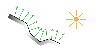
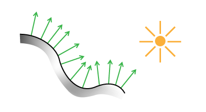 Lighting a surface using its normals.
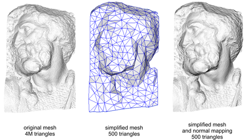
 Lighting a low-resolution surface using high-resolution normals.
 (
(
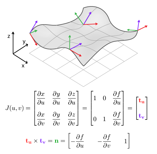
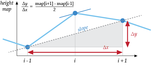
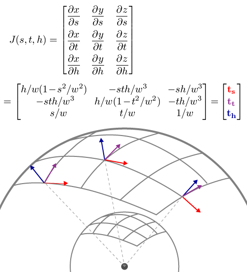 PS: If your skills at derivation are a bit rusty, remember that
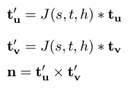

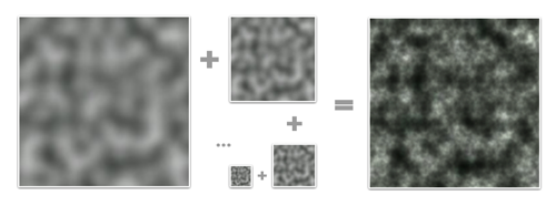

 Rendering two different cube map faces. The red area is the camera's viewing cone/pyramid, which extends out to infinity.