<?xml version="1.0" encoding="utf-8"?>
<feed xmlns="http://www.w3.org/2005/Atom">

  <title><![CDATA[Acko.net]]></title>
  <link href="http://acko.net/atom.xml" rel="self"/>
  <link href="http://acko.net/"/>
  <updated>2012-05-17T01:12:29-07:00</updated>
  <id>http://acko.net/</id>
  <author>
    <name><![CDATA[Steven Wittens]]></name>
    
  </author>

  
  <entry>
    <title type="html"><![CDATA[On TermKit]]></title>
    <link href="http://acko.net/blog/on-termkit/"/>
    <updated>2011-05-17T00:00:00-07:00</updated>
    <id>http://acko.net/blog/on-termkit</id>
    <content type="html"><![CDATA[<div class='g8 i2 first'><div class='pad'>
  
<h1>On TermKit</h1>

<p>I've been administering Unix machines for many years now, and frankly, it kinda sucks. It makes me wonder, when sitting in front of a crisp, 2.3 million pixel display (i.e. a laptop) why I'm telling those pixels to draw me a computer terminal from the 80s.
</p>

<p>
<img alt='Regular bash terminal' src='/files/termkit/termkit-1.png' />
</p>

<p>
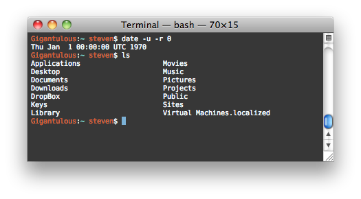
And yet, that's what us tech nerds do every day. The default Unix toolchain, marked in time by the 1970 epoch, operates in a world where data is either binary or text, and text is displayed in monospace chunks. The interaction is strictly limited to a linear flow of keystrokes, always directed at only one process. And that process is capable of communicating only in short little grunts of text, perhaps coalescing into a cutesy little ASCII art imitation of things that grown-ups call "dialogs", "progress bars", "tables" and "graphs".
</p>

<p>
The <a href='http://www.faqs.org/docs/artu/ch01s06.html'>Unix philosophy</a> talks about software as a toolset, about tiny programs that can be composed seamlessly. The principles are sound, and have indeed stood the test of time. But they were implemented in a time when computing resources were orders of magnitude smaller, and computer interaction was undiscovered country.
</p>

<p>
In the meantime, we've gotten a lot better at displaying information. We've also learned a lot of lessons through the web about data interchange, network transparency, API design, and more. We know better how small tweaks in an implementation can make a world of difference in usability.
</p>

<p>
And yet the world of Unix is rife with jargon, invisible processes, traps and legacy bits. Every new adept has to pass a constant trial by fire, of not destroying their system at every opportunity it gives them.
</p>

<p>
So while I agree that having a flexible toolbox is great, in my opinion, those pieces could be built a lot better. I don't want the computer equivalent of a screwdriver and a hammer, I want a tricorder and a laser saw. TermKit is my attempt at making these better tools and addresses a couple of major pain points.
</p>

<p>
I see TermKit as an extension of what Apple did with OS X, in particular the system tools like Disk Utility and Activity Monitor. Tech stuff doesn't have to look like it comes from the Matrix.
</p>

<h2>Rich Display</h2>

<p>
It's 2011, and monospace text just doesn't cut it anymore. In the default ANSI color palette, barely any of the possible color combinations are even readable. We can't display graphs, mathematical formulas, tables, etc. We can't use the principles of modern typography to lay out information in a readable, balanced way.
</p>

<p>
<img alt='TermKit example' src='/files/termkit/termkit-2.png' />
</p>

<p>
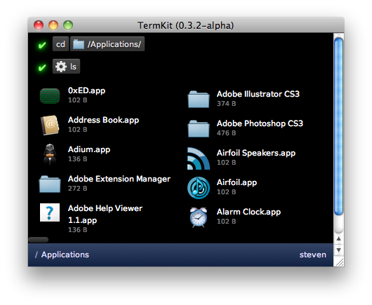
So instead, I opted for a front-end built in WebKit. Programs can display anything that a browser can, including HTML5 media. The output is built out of generic widgets (lists, tables, images, files, progress bars, etc.). The goal is to offer a rich enough set for the common data types of Unix, extensible with plug-ins. The back-end streams display output to the front-end, as a series of objects and commands.
</p>

<p>
I should stress that despite WebKit it is not my intent to make HTML the lingua franca of Unix. The front-end is merely implemented in it, as it makes it instantly accessible to anyone with HTML/CSS knowledge.
</p>

<h2>Pipes</h2>

<p>
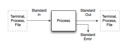
  Unix pipes are anonymous binary streams, and each process comes with at least three: Standard In, Standard Out and Standard Error. This corresponds to the typical <em>Input</em> > <em>Processing</em> > <em>Output</em> model, with an additional error channel. However, in actual usage, there are two very different scenarios.
</p>

<p>
<img alt='' src='/files/termkit/termkit-3.png' />
</p>

<p>
One is the case of interactive usage: a human watches the program output (from Std Out) on a display, and types keystrokes to interact with it (into Std In). Another case is the data processing job: a program accepts a data stream in a particular format on Std In, and immediately outputs a related data stream on Std Out. These two can be mixed, in that a chain of piped commands can have a human at either end, though usually this implies non-interactive operation.
</p>

<p>
These two cases are shoehorned into the same pipes, but happen quite differently. Human input is spontaneous, sporadic and error prone. Data input is strictly formatted and continuous. Human output is ambiguous, spaced out and wordy. Data output is conservative and monolithic.
</p>

<p>
As a result, many Unix programs have to be careful about data. For example, many tools dynamically detect whether they are running in interactive mode, and adjust their output to be more human-friendly or computer-friendly. Other tools come with flags to request the input/output in specific formats.
</p>

<p>
This has lead to "somewhat parseable text" being the default interchange format of choice. This seems like an okay choice, until you start to factor in the biggest lesson learned on the web: there is no such thing as plain text. Text is messy. Text-based formats lie at the basis of every SQL injection, XSS exploit and encoding error. And it's in text-parsing code where you'll likely find buffer overflows.
</p>

<p>
What this means in practice is that in every context, there are some forbidden characters, either by convention or by spec. For example, no Unicode or spaces in filenames. In theory, it's perfectly fine, but in practice, there's at least one shell script on your system that would blow up if you tried. Despite the promise of text as the universal interchange format, we've been forced to impose tons of vague limits.
</p>

<p>
So how do we fix this? By separating the "data" part from the "human" part. Then we can use messy text for humans, and pure data for the machines. Enter "Data In/Out", "View In/Out".
</p>

<p>
<img alt='TermKit data flow diagram' src='/files/termkit/termkit-4.png' />
</p>

<p>
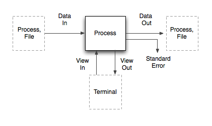
The data pipes correspond to the classical Std pipes, with one difference: the stream is prefixed with MIME-like headers (Content-Type, Content-Length, etc). Of these, only the 'Content-Type' is required. It allows programs to know what kind of input they're receiving, and handle it graciously without sniffing. Aside from that, the data on the pipe is a raw binary stream.
</p>

<p>
The view pipes carry the display output and interaction to the front-end. Widgets and UI commands are streamed back and forth as JSON messages over the view pipes.
</p>

<p>
The real magic happens when these two are combined. The last dangling Std Out pipe of any command chain needs to go into the Terminal, to be displayed as output. But the data coming out of Data Out is not necessarily human-friendly.
</p>

<p>
Thanks to the MIME-types, we can solve this universally. TermKit contains a library of output formatters which each handle a certain type of content (text, code, images, ...). It selects the right formatter based on the Content-Type, which then generates a stream of view updates. These go over the View Out pipe and are added to the command output.
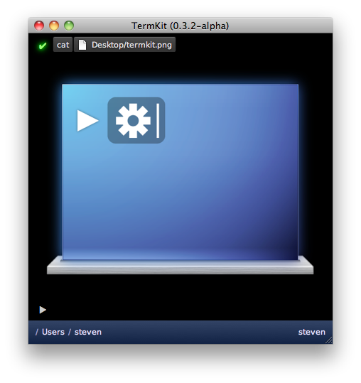
</p>

<p>
<img alt='Cat&apos;ing an image' src='/files/termkit/termkit-7.png' />
</p>

<p>
As a result, you can <code>cat</code> a PNG and have it just work. TermKit <code>cat</code> doesn't know how to process PNGs or HTML—it only guesses the MIME type based on the filename and pipes the raw data to the next process. Then the formatter sends the image to the front-end. If you <code>cat</code> a source code file, it gets printed with line numbers and syntax highlighting.
</p>

<p>
So where does "somewhat parseable text" fit in? It turns out to be mostly unnecessary. Commands like <code>ls</code> output structured data by nature, i.e. a listing of files from one or more locations. It makes sense to pipe around this data in machine-form. Output flags like <code>ls&nbsp;-l</code> become mere hints for the final display, which can toggle on-the-fly between compact and full listing.
</p>

<p>
In TermKit's case, JSON is the interchange format of choice. The <code>Content-Type</code> for file listings is <code>application/json;&nbsp;schema=termkit.files</code>. The <code>schema</code> acts as a marker to select the right output plug-in. In this case, we want the file formatter rather than the generic raw JSON formatter.
</p>

<p>
<img alt='Formatting data in TermKit' src='/files/termkit/termkit-8.png' />
</p>

<p>
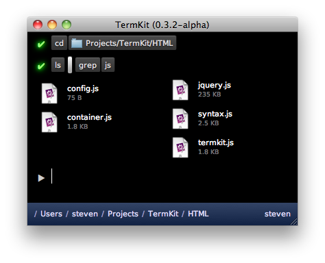
Isn't JSON data harder to work with than lines of text? Only in some ways, but parsing JSON is trivial these days in any language. Because of this, I built TermKit <code>grep</code> so it supports grepping JSON data recursively. This happens transparently when the input is <code>application/json</code> instead of <code>text/plain</code>. As a result <code>ls&nbsp;|&nbsp;grep</code> works as you'd expect it to.
</p>

<p>
To slot in traditional Unix utilities in this model, we can pipe their data as <code>application/octet-stream</code> to start with, and enhance specific applications with type hints and wrapper scripts.
</p>

<p>
<img alt='' src='/files/termkit/termkit-6.png' />
</p>

<p>
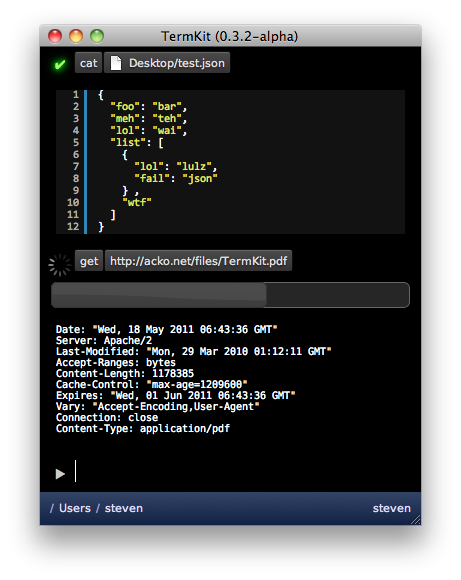
Finally, having type annotations on pipes opens up another opportunity: it allows us to pipe in HTTP GET / POST requests almost transparently. Getting a URL becomes no different from catting a file, and both can have fancy progress bars, even when inside a pipe chain like <code>get&nbsp;|&nbsp;grep</code>.
</p>

<h2>Synchronous interaction</h2>

<p>
All interaction in a traditional terminal is synchronous. Only one process is interactive at a time, and each keystroke must be processed by the remote shell before it is displayed. This leads to an obvious daily frustration: SSH keystroke lag.
</p>

<p>
To fix this, TermKit is built out of a separate front-end and back-end. The front-end can run locally, controlling a back-end on a remote machine. The connection can be tunneled over SSH for security.
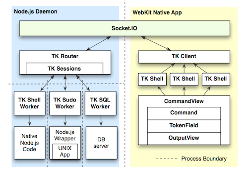
</p>

<p class='tc'>
<a href='https://github.com/unconed/TermKit/raw/master/Mockups/Architecture.pdf'><img alt='TermKit architecture' src='/files/termkit/termkit-9.png' />Architecture diagram</a> (TK stands for TermKit)
</p>

<p>
Additionally, all display updates and queries are asynchronous. The WebKit-based HTML display is split up into component views, and the view pipes of each subprocess are routed to their own view. Vice-versa, any interactive widgets inside a view can send callback messages back to their origin process, as long as it's still running.
</p>

<p>
This also allows background processes to work without overflowing the command prompt.
</p>

<h2>String-based command line</h2>

<p>
A lot of my frustration comes from bash's arcane syntax. It has a particularly nasty variant of C-style escaping. Just go ahead and <em>try</em> to match a regular expression involving both types of quotes.
</p>

<p>
But at its core, a bash command is a series of tokens. Some tokens are single words, some are flags, some are quoted strings, some are modifiers (like | and >). It makes sense for the input to reflect this.
</p>

<p>
<img alt='TermKit command-line' src='/files/termkit/termkit-5.png' />
</p>

<p>
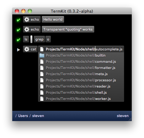
TermKit's input revolves around tokenfield.js, a new snappy widget with plenty of tricks. It can do auto-quoting, inline autocomplete, icon badges, and more. It avoids the escaping issue altogether, by always processing the command as tokens rather than text. Keys that trigger special behaviors (like a quote) can be pressed again to undo the behavior and just type one character.
</p>

<p>
The behaviors are encoded in a series of objects and regexp-based triggers, which transform and split tokens as they are typed. That means it's extensible too.
</p>

<h2>Usability</h2>

<p>
At the end of the day, Unix just has bad usability. It tricks us with unnecessary abbreviations, inconsistent arguments (-r vs -R) and nitpicky syntax. Additionally, Unix has a habit of giving you raw data, but not telling you useful facts, e.g. 'r-xr-xr-x' instead of "You can't touch this" (<em>ba-dum tsshh</em>).
</p>

<p>
One of the Unix principles is nobly called "Least Surprise", but in practice, from having observed new Unix users, I think it often becomes "Maximum Confusion". We should be more pro-active in nudging our users in the right direction, and our tools should be designed for maximum discoverability.
</p>

<p>
For example, I want to see the relevant part of a man page in a tooltip when I'm typing argument switches. I'd love for dangerous flags to be highlighted in red. I'd love to see regexp hints of possible patterns inline.
</p>

<p>
There's tons to be done here, but we can't do anything without modern UI abilities.
</p>

<h2>Focus and Status</h2>

<p>
With a project like TermKit, it's easy to look at the shiny exterior and think "meh", or that I'm just doing things differently for difference's sake. But to me, the real action is under the hood. With a couple of tweaks and some uncompromising spring cleaning, we can get Unix to do a lot more for us.
</p>

<p>
The current version of TermKit is just a rough alpha, and what it does is in many ways just parlour tricks compared to what it could be doing in a few months. The architecture definitely supports it.
</p>

<p>
I've worked on TermKit off and on for about a year now, so I'd love to hear feedback and ideas. Please <a href='http://github.com/unconed/TermKit'>go check out the code</a>.
</p>

<p>
TermKit owes its existence to Node.js, Socket.IO, jQuery and WebKit. Thanks to everyone who has contributed to those projects.
</p>

<p>
<em>Edit, a couple of quick points:</em>
</p>

<ul>
<li>A Linux port will definitely happen, since it's built out of WebKit and Node.js. Whoever does it first gets a cookie.</li>
<li>TermKit is not tied to JSON except in its own internal communication channels. TermKit Pipes can be in any format, and old-school plain-text still works. JSON just happens to be very handy and very lightweight.</li>
<li>The current output is just a proof of concept and lacks many planned usability enhancements. There are mockups on github.</li>
<li>If you're going to tell me I'm stupid, please read all the other 100 comments doing so first, so we can keep this short for everyone else.</li>
</ul>

<p>
<em>Edit, random fun:</em>
</p>

<p>Someone asked for AVS instead of TermKit in the comments... best I could do was JS1K with a PDF surprise:</p>

<iframe allowfullscreen='allowfullscreen' frameborder='0' height='349' src='http://www.youtube.com/embed/dAeZTgRuWsU' style='margin: 0 auto;' width='425' />

<iframe allowfullscreen='allowfullscreen' frameborder='0' height='349' src='http://www.youtube.com/embed/_6Z5dnlfcls' width='560' />

</div></div>]]></content>
  </entry>
  
  <entry>
    <title type="html"><![CDATA[My JS1K Demo - The Making Of]]></title>
    <link href="http://acko.net/blog/js1k-demo-the-making-of/"/>
    <updated>2010-08-06T00:00:00-07:00</updated>
    <id>http://acko.net/blog/js1k-demo-the-making-of</id>
    <content type="html"><![CDATA[<div class='g8 i2 first'><div class='pad'>
  
<h1>My JS1K Demo - The Making Of</h1>

<p>If you haven't seen it yet, check out the <a href='http://js1k.com'>JS1K demo contest</a>. The goal is to do something neat in 1 kilobyte of JavaScript code.</p>
<p>I couldn't resist making one myself, so I pulled out my bag of tricks from my <a href='/design/avs'>Winamp music visualization</a> days and started coding. I'm really happy with how it turned out. And no, it won't work in Internet Explorer 8 or less.</p>

<p><em>Edit: OH SNAP! I just rewrote the demo to include volumetric light beams and still fit in 1K:</em></p>

</div></div><div class='g6'><div class='pad'>

<h3>Original Version</h3>
<p><iframe frameborder='0' height='345' id='1kjs' src='about:blank' style='background:#000;border:0' width='510' /></p>
<p><button id='1kjs-stop' onclick='$(&apos;#1kjs&apos;).attr(&apos;src&apos;,&apos;about:blank&apos;);$(this).hide();$(&apos;#1kjs-start&apos;).show();' style='display: none'>Stop Demo</button><button id='1kjs-start' onclick='$(&apos;#1kjs&apos;).attr(&apos;src&apos;,&apos;/files/making-of-js1k/1022b.html&apos;);$(this).hide();$(&apos;#1kjs-stop&apos;).show();'>Start Demo</button><button onclick='$(&apos;#1kjs&apos;).attr(&apos;src&apos;,&apos;/files/making-of-js1k/1022s.html&apos;);$(&apos;#1kjs-start&apos;).show();$(&apos;#1kjs-stop&apos;).hide();'>View Source</button></p>

</div></div><div class='g6'><div class='pad'>

<h3>Improved Version</h3>

<p><iframe frameborder='0' height='345' id='1kjs2' src='about:blank' style='background:#000;border:0' width='510' /></p>
<p><button id='1kjs2-stop' onclick='$(&apos;#1kjs2&apos;).attr(&apos;src&apos;,&apos;about:blank&apos;);$(this).hide();$(&apos;#1kjs2-start&apos;).show();' style='display: none'>Stop Demo</button><button id='1kjs2-start' onclick='$(&apos;#1kjs2&apos;).attr(&apos;src&apos;,&apos;/files/making-of-js1k/1024b.html&apos;);$(this).hide();$(&apos;#1kjs2-stop&apos;).show();'>Start Demo</button><button onclick='$(&apos;#1kjs2&apos;).attr(&apos;src&apos;,&apos;/files/making-of-js1k/1024s.html&apos;);$(&apos;#1kjs2-start&apos;).show();$(&apos;#1kjs2-stop&apos;).hide();'>View Source</button></p>

</div></div><div class='g8 i2'><div class='pad'>

<p>Now, whenever size is an issue, the best way to make a small program is to generate all data on the fly, i.e. procedurally. This saves valuable storage space. While this might seem like a black art, often it just comes down to clever use of (high school) math. And as is often the case, the best tricks are also the simplest, as they use the least amount of code.</p>
<p>To illustrate this, I'm going to break down my demo and show you all the major pieces and shortcuts used. Unlike the actual 1K demo, the code snippets here will feature legible spacing and descriptive variable names.</p>

<h3>Initialization</h3>

<p>JS1K's rules give you a Canvas tag to work with, so the first piece of code initializes it and makes it fill the window.</p>
<p>From then on, it just renders frames of the demo. There are four major parts to this:</p>
<ul>
<li>Animating the wires</li>
<li>Rotating and projecting the wires into the camera view</li>
<li>Coloring the wires</li>
<li>Animating the camera</li>
</ul>
<p>All of this is done 30 times per second, using a normal <code>setInterval</code> timer:</p>
<p class='codeblock'><code>setInterval(function () { ... }, 33);</code></p>

<h3>Drawing Wires</h3>

<p>The most obvious trick is that everything in the demo is drawn using only a single primitive: a line segment of varying color and stroke width. This allows the whole drawing process to be streamlined into two tight, nested loops. Each inner iteration draws a new line segment from where the previous one ended, while the outer iteration loops over the different wires.</p>

<p><img alt='drawing process for demo' src='/files/making-of-js1k/drawing-process.png' title='Drawing each wire in sequence.' /></p>

<p>The lines are blended additively, using the built-in 'lighten' mode, which means they can be drawn in any order. This avoids having to manually sort them back-to-front.</p>
<p>To simplify the perspective transformations, I use a coordinate system that places the point (0, 0) in the center of the canvas and ranges from -1 to 1 in both coordinates. This is a compact and convenient way of dealing with varying window sizes, without using up a lot of code:</p>
<p class='codeblock'><code>with (graphics) {<br />&nbsp; ratio = width / height;<br />&nbsp; globalCompositeOperation = &#039;lighter&#039;;<br />&nbsp; scale(width / 2 / ratio, height / 2);<br />&nbsp; translate(ratio, 1);<br />&nbsp; lineWidthFactor = 45 / height;<br />&nbsp; ...</code></p>
<p>I also add a correction <code>ratio</code> for non-square windows and calculate a reference line width <code>lineWidthFactor</code> for later.</p>
<p>Then there's the two nested <code>for</code> loops: one iterating over the wires, and one iterating over the individual points along each wire. In pseudo-code they look like:</p>
<p class='codeblock'><code>For (12 wires =&gt; wireIndex) {<br />&nbsp; Begin new wire<br />&nbsp; For (45 points along each wire =&gt; pointIndex) {<br />&nbsp;&nbsp;&nbsp; Calculate path of point on a sphere: (x,y,z)<br />&nbsp;&nbsp;&nbsp; Extrude outwards in swooshes: (x,y,z)<br />&nbsp;&nbsp;&nbsp; Translate and Rotate into camera view: (x,y,z)<br />&nbsp;&nbsp;&nbsp; Project to 2D: (x,y)<br />&nbsp;&nbsp;&nbsp; Calculate color, width and luminance of this line: (r,g,b) (w,l)<br />&nbsp;&nbsp;&nbsp; If (this point is in front of the camera) {<br />&nbsp;&nbsp;&nbsp;&nbsp;&nbsp; If (the last point was visible) {<br />&nbsp;&nbsp;&nbsp;&nbsp;&nbsp;&nbsp;&nbsp; Draw line segment from last point to (x,y)<br />&nbsp;&nbsp;&nbsp;&nbsp;&nbsp; }<br />&nbsp;&nbsp;&nbsp; }<br />&nbsp;&nbsp;&nbsp; else {<br />&nbsp;&nbsp;&nbsp;&nbsp;&nbsp; Mark this point as invisible<br />&nbsp;&nbsp;&nbsp; }<br />&nbsp;&nbsp;&nbsp; Mark beginning of new line segment at (x,y)<br />&nbsp; }<br />}</code></p>

<h3>Mathbending</h3>

<p>To generate the wires, I start with a formula which generates a sinuous path on a sphere, using latitude/longitude. This controls the tip of each wire and looks like:</p>
<p class='codeblock'><code>offset = time - pointIndex * 0.03 - wireIndex * 3;<br />longitude = cos(offset + sin(offset * 0.31)) * 2<br />&nbsp;&nbsp;&nbsp;&nbsp;&nbsp;&nbsp;&nbsp;&nbsp;&nbsp; + sin(offset * 0.83) * 3 + offset * 0.02;<br />latitude = sin(offset * 0.7) - cos(3 + offset * 0.23) * 3;</code></p>
<p>This is classic procedural coding at its best: take a time-based <code>offset</code> and plug it into a random mish-mash of easily available functions like cosine and sine. Tweak it until it 'does the right thing'. It's a very cheap way of creating interesting, organic looking patterns.</p>
<p>This is more art than science, and mostly just takes practice. Any time spent with a graphical calculator will definitely pay off, as you will know better which mathematical ingredients result in which shapes or patterns. Also, there are a couple of things you can do to maximize the appeal of these formulas.</p>
<p>First, always include some non-linear combinations of operators, e.g. nesting the sin() inside the cos() call. Combined, they are more interesting than when one is merely overlaid on the other. In this case, it turns regular oscillations into time-varying frequencies.</p>
<p>Second, always scale different wave periods using prime numbers. Because primes have no factors in common, this ensures that it takes a very long time before there is a perfect repetition of all the individual periods. Mathematically, the <a href='http://www.wolframalpha.com/input/?i=%28least+common+multiple+of+%28100+31+83+70+23%29%29+%2F+100'>least common multiple of the chosen periods</a> is huge (414253 units ~ 4.8 hours). Plotting the longitude/latitude for <code>offset = 0..600</code> you get:</p>
<p><img alt='a pseudo-random set of oscillations' src='/files/making-of-js1k/js1k-2.jpg' title='Looks pretty random' /></p>
<p>The graph looks like a random tangled curve, with no apparent structure, which makes for motions that never seem to repeat. If however, you reduce each constant to only a single significant digit (e.g. 0.31 -> 0.3, 0.83 -> 0.8), then suddenly repetition becomes apparent:</p>
<p><img alt='a not so pseudo-random set of oscillations' src='/files/making-of-js1k/js1k-3.jpg' title='Not so random' /></p>
<p>This is because the least common multiple has <a href='http://www.wolframalpha.com/input/?i=%28least+common+multiple+of+%28100+30+80+70+20%29%29+%2F+100'>dropped to 84 units ~ 3.5 seconds</a>. Note that both formulas have the same code complexity, but radically different results. This is why all procedural coding involves some degree of creative fine tuning.</p>
<h3>Extrusion</h3>

<p>Given the formula for the tip of each wire, I can generate the rest of the wire by sweeping its tail behind it, delayed in time. This is why <code>pointIndex</code> appears as a negative in the formula for <code>offset</code> above. At the same time, I move the points outwards to create long tails.</p>
<p>I also need to convert from lat/long to regular 3D XYZ, which is done using the <a href='http://en.wikipedia.org/wiki/Spherical_coordinate_system'>spherical coordinate transform</a>:</p>
<p><img alt='spherical coordinates' src='/files/making-of-js1k/js1k-4.jpg' /><center>Source: <a href='http://en.wikipedia.org/wiki/File:Coord_system_SE_0.svg'>Wikipedia</a></center></p>
<p class='codeblock'><code>distance = f.sqrt(pointIndex+.2);<br />x = cos(longitude) * cos(latitude) * distance;<br />y = sin(longitude) * cos(latitude) * distance;<br />z = sin(latitude) * distance;</code></p>
<p>You might notice that rather than making <code>distance</code> a straight up function of the length <code>pointIndex</code> along the wire, I applied a square root. This is another one of those procedural tricks that seems arbitrary, but actually serves an important visual purpose. This is what the square root looks like (solid curve):</p>
<p><img alt='square root' src='/files/making-of-js1k/js1k-5.jpg' /></p>
<p>The dotted curve is the square root's derivative, i.e. it indicates the slope of the solid curve. Because the slope goes down with increasing distance, this trick has the effect of slowing down the outward motion of the wires the further they get. In practice, this means the wires are more tense in the middle, and more slack on the outside. It adds just enough faux-physics to make the effect visually appealing.</p>
<h3>Rotation and Projection</h3>

<p>Once I have absolute 3D coordinates for a point on a wire, I have to render it from the camera's point of view. This is done by moving the origin to the camera's position (X,Y,Z), and applying two rotations: one around the vertical (yaw) and one around the horizontal (pitch). It's like spinning on a wheely chair, while tilting your head up/down.</p>
<p class='codeblock'><code>x -= X; y -= Y; z -= Z;<br /><br />x2 = x * cos(yaw) + z * sin(yaw);<br />y2 = y;<br />z2 = z * cos(yaw) - x * sin(yaw);<br /><br />x3 = x2;<br />y3 = y2 * cos(pitch) + z2 * sin(pitch);<br />z3 = z2 * cos(pitch) - y2 * sin(pitch);</code></p>
<p>The camera-relative coordinates are projected in perspective by dividing by Z — the further away an object, the smaller it is. Lines with negative Z are behind the camera and shouldn't be drawn. The width of the line is also scaled proportional to distance, and the first line segment of each wire is drawn thicker, so it looks like a plug of some kind:</p>
<p class='codeblock'><code>plug = !pointIndex;<br />lineWidth = lineWidthFactor * (2 + plug) / z3;<br />x = x3 / z3;<br />y = y3 / z3;<br /><br />lineTo(x, y);<br />if (z3 &gt; 0.1) {<br />&nbsp; if (lastPointVisible) {<br />&nbsp;&nbsp;&nbsp; stroke();<br />&nbsp; }<br />&nbsp; else {<br />&nbsp;&nbsp;&nbsp; lastPointVisible = true;<br />&nbsp; }<br />}<br />else {<br />&nbsp; lastPointVisible = false;<br />}<br />beginPath();<br />moveTo(x, y);</code></p>
<h3>Coloring</h3>
<p>Each line segment also needs an appropriate coloring. Again, I used some trial and error to find a simple formula that works well. It uses a sine wave to rotate overall luminance in and out of the (Red, Green, Blue) channels in a deliberately skewed fashion, and shifts the R component slowly over time. This results in a nice varied palette that isn't overly saturated.</p>
<p class='codeblock'><code>pulse = max(0, sin(time * 6 - pointIndex / 8) - 0.95) * 70;<br />luminance = round(45 - pointIndex) * (1 + plug + pulse);<br />strokeStyle=&#039;rgb(&#039; + <br />&nbsp; round(luminance * (sin(plug + wireIndex + time * 0.15) + 1)) + &#039;,&#039; + <br />&nbsp; round(luminance * (plug + sin(wireIndex - 1) + 1)) + &#039;,&#039; +<br />&nbsp; round(luminance * (plug + sin(wireIndex - 1.3) + 1)) +<br />&nbsp; &#039;)&#039;;</code></p>
<p>Here, <code>pulse</code> causes bright pulses to run across the wires. I start with a regular sine wave over the length of the wire, but truncate off everything but the last 5% of each crest to turn it into a sparse pulse train:</p>
<p><img alt='sine pulse train' src='/files/making-of-js1k/js1k-6.jpg' /></p>
<h3>Camera Motion</h3>

<p>With the main visual in place, almost all my code budget is gone, leaving very little room for the camera. I need a simple way to create consistent motion of the camera's X, Y and Z coordinates. So, I use a neat low-tech trick: repeated interpolation. It looks like this:</p>
<p class='codeblock'><code>sample += (target - sample) * fraction</code></p>
<p><code>target</code> is set to a random value. Then, every frame, <code>sample</code> is moved a certain fraction towards it (e.g. <code>0.1</code>). This turns <code>sample</code> into a smoothed version of <code>target</code>. Technically, this is a <em>one-pole low-pass filter</em>.</p>
<p>This works even better when you apply it twice in a row, with an intermediate value being interpolated as well:</p>
<p class='codeblock'><code>intermediate += (target - intermediate) * fraction<br />sample += (intermediate - sample) * fraction</code></p>
<p>A sample run with <code>target</code> being changed at random might look like this:</p>
<p><img alt='sine pulse train' src='/files/making-of-js1k/js1k-7.jpg' /></p>
<p>You can see that with each interpolation pass, more discontinuities get filtered out. First, jumps are turned into kinks. Then, those are smoothed out into nice bumps.</p>
<p>In my demo, this principle is applied separately to the camera's X, Y and Z positions. Every ~2.5 seconds a new target position is chosen:</p>
<p class='codeblock'><code>if (frames++ &gt; 70) {<br />&nbsp; Xt = random() * 18 - 9;<br />&nbsp; Yt = random() * 18 - 9;<br />&nbsp; Zt = random() * 18 - 9;<br />&nbsp; frames = 0;<br />}<br /><br />function interpolate(a,b) {<br />&nbsp; return a + (b-a) * 0.04;<br />}<br /><br />Xi = interpolate(Xi, Xt);<br />Yi = interpolate(Yi, Yt);<br />Zi = interpolate(Zi, Zt);<br /><br />X&nbsp; = interpolate(X,&nbsp; Xi);<br />Y&nbsp; = interpolate(Y,&nbsp; Yi);<br />Z&nbsp; = interpolate(Z,&nbsp; Zi);</code></p>
<p>The resulting path is completely smooth and feels quite dynamic.</p>
<h3>Camera Rotation</h3>

<p>The final piece is orienting the camera properly. The simplest solution would be to point the camera straight at the center of the object, by calculating the appropriate <code>pitch</code> and <code>yaw</code> directly off the camera's position (X,Y,Z):</p>
<p class='codeblock'><code>yaw&nbsp;&nbsp; = atan2(Z, -X);<br />pitch = atan2(Y, sqrt(X * X + Z * Z));</code></p>
<p>However, this gives the demo a very static, artificial appearance. What's better is making the camera point in the right direction, but with just enough freedom to pan around a bit.</p>
<p>Unfortunately, the 1K limit is unforgiving, and I don't have any space to waste on more 'magic' formulas or interpolations. So instead, I cheat by replacing the formulas above with:</p>
<p class='codeblock'><code>yaw&nbsp;&nbsp; = atan2(Z, -X * 2);<br />pitch = atan2(Y * 2, sqrt(X * X + Z * Z));</code></p>
<p>By multiplying X and Y by 2 strategically, the formula is 'wrong', but the error is limited to about 45 degrees and varies smoothly. Essentially, I gave the camera a lazy eye, and got the perfect dynamic motion with only 4 bytes extra!</p>
<h3>Addendum</h3>

<p>After seeing the other demos in the contest, I wasn't so sure about my entry, so I started working on a version 2. The main difference is the addition of glowy light beams around the object.</p>
<p>As you might suspect, I'm cheating massively here: rather than do physically correct light scattering calculations, I'm just using a 2D effect. Thankfully it comes out looking great.</p>
<p>Essentially, I take the rendered image, and process it in a second Canvas that is hidden. This new image is then layered on the original.</p>
<p>I take the image and repeatedly blend it with a zoomed out copy of itself. With every pass the number of copies doubles, and the zoom factor is squared every time. After 3 passes, the image has been smeared out into an 8 = 2<sup>3</sup> 'tap' radial blur. I lock the zooming to the center of the 3D object. This makes the beams look like they're part of the 3D world rather than drawn on later.</p>
<p>For additional speed, the beam image is processed at half the resolution. As a side effect, the scaling down acts like a slight blur filter for the beams.</p>
<p>Unfortunately, this effect was not very compact, as it required a lot of drawing mode changes and context switches. I had no room for it  in the source code.</p>
<p>So, I had to squeeze out some more room in the original. First, I simplified the various formulas to the bare minimum required for interesting visuals. I replaced the camera code with a much simpler one, and started aggressively shaving off every single byte I could find. Then I got creative, and ended up recreating the secondary canvas every frame just to avoid switching back its state to the default.</p>
<p>Eventually, after a lot of bit twiddling, a version came out that was 1024 bytes long. I had to do a lot of unholy things to get it to fit, but I think the end result is worth it ;). </p>
<h3>Closing Thoughts</h3>

<p>I've long been a fan of the demo scene, and fondly remember <a href='http://www.youtube.com/watch?v=dQveVMQDJlg'>Second Reality</a> in 1993 as my introduction to the genre. Since then, I've always looked at math as a tool to be mastered and wielded rather than subject matter to be absorbed.</p>
<p>With this blog post, I hope to inspire you to take the plunge and see where some simple formulas can take you.</p>

</div></div>]]></content>
  </entry>
  
  <entry>
    <title type="html"><![CDATA[Making Worlds 4 - The Devil's in the Details]]></title>
    <link href="http://acko.net/blog/making-worlds-4-the-devils-in-the-details/"/>
    <updated>2009-12-25T00:00:00-08:00</updated>
    <id>http://acko.net/blog/making-worlds-4-the-devils-in-the-details</id>
    <content type="html"><![CDATA[<div class='g8 i2 first'><div class='pad'><h1>Making Worlds 4 - The Devil's in the Details</h1>
  
<aside class='r'><img alt='' src='/files/making-worlds/planet-3-th.jpg' /></aside>

<p>Last time I'd reached a pretty neat milestone: being able to render a somewhat realistic rocky surface from space. The next step is to add more detail, so it still looks good up close.
</p>

<p>
Adding detail is, at its core, quite straightforward. I need to increase the resolution of the surface textures, and further subdivide the geometry. Unfortunately I can't just crank both up, because the resulting data is too big to fit in graphics memory. Getting around this will require several changes.
</p>

<h3>Strategy</h3>

<p>
Until now, the level-of-detail selection code has only been there to decide which portions of the planet should be <em>drawn</em> on screen. But the geometry and textures to choose from are all prepared up front, at various scales, before the first frame is started. The surface is generated as one high-res planet-wide map, using typical cube map rendering:
</p>

<p>
<img alt='' src='/files/making-worlds/cubemap-rendering.png' title='Rendering an entire cube face at a time' />
</p>

<p>
This map is then divided into a quad-tree structure of surface tiles. It allows me to adaptively draw the surface at several pre-defined levels of detail, in chunks of various sizes.
<!--break-->
</p>

<p class='tc'>
<img alt='Quadtree terrain' src='/files/making-worlds/planets-1-quadtree.png' /><small><a href='http://tulrich.com/geekstuff/sig-notes.pdf'>Source</a></small>
</p>

<p>
This strategy won't suffice, because each new level of detail doubles the work up-front, resulting in exponentially increasing time and memory cost. Instead, I need to write an adaptive system to generate and represent the surface on the fly. This process is driven by the Level-of-Detail algorithm deciding if it needs more detail in a certain area. Unlike before, it will no longer be able to make snap decisions and instant transitions between pre-loaded data: it will need to wait several frames before higher detail data is available.
</p>

<p>
<img alt='Configuration of chunks to render' src='/files/making-worlds/planet-lod-tree.png' />
</p>

<p>
Uncontrolled growth of increasingly detailed tiles is not acceptable either: I only wish to maintain tiles useful for rendering views from the current camera position. So if a specific detailed portion of the planet is no longer being used—because the camera has moved away from it—it will be discarded to make room for other data.
</p>

<h2>Generating Individual Tiles</h2>

<p>
The first step is to be able to generate small portions of the surface on demand. Thankfully, I don't need to change all that much. Until now, I've been generating the cube map one cube face at a time, using a virtual camera at the middle of the cube. To generate only a portion of the surface, I have to narrow the virtual camera's viewing cone and skew it towards a specific point, like so:
</p>

<p>
<img alt='' src='/files/making-worlds/cubemap-rendering-subdivision.png' title='Rendering one face tile at a time' />
</p>

<p>
This is easy using a mathematical trick called <a href='http://en.wikipedia.org/wiki/Homogeneous_coordinates'>homogeneous coordinates</a>, which are commonly used in 3D engines. This turns 2D and 3D vectors into respectively 3D and 4D. Through this dimensional redundancy, we can then represent most geometrical transforms as a 4x4 matrix multiplication. This covers all transforms that translate, scale, rotate, shear and project, in any combination. The right sequence (i.e. multiplication) of transforms will map regular 3D space onto the skewed camera viewing cone.
</p>

<p>
Given the usual centered-axis projection matrix, the off-axis projection matrix is found by multiplying with a scale and translate matrix in so-called "screen space", i.e. at the very end. The thing with homogeneous coordinates is that it seems like absolute crazy talk until you get it. I can only recommend you read a <a href='http://www.cim.mcgill.ca/~langer/558/lecture3.pdf'>good introduction to the concept</a>.
</p>

<p>
With this in place, I can generate a zoomed height map tile anywhere on the surface. As long as the underlying brushes are detailed enough, I get arbitrarily detailed height textures for the surface. The normal map requires a bit more work however. 
</p>

<h3>Normals and Edges</h3>

<p>
As I described in <a href='http://acko.net/blog/making-worlds-3-thats-no-moon'>my last entry</a>, normals are generated by comparing neighbouring samples in the height map. At the edges of the height map texture, there are no neighbouring samples to use. This wasn't an issue before, because the height map was a seamless planet-wide cube map, and samples were fetched automatically from adjacent cube faces. In an adaptive system however, the map resolution varies across the surface, and there's no guarantee that those neighbouring tiles will be available at the desired resolution.
</p>

<p>
The easy way out is to make sure the process of generating any single tile is entirely self-sufficient. To do this, I expand each tile with a 1 pixel border when generating it. Each such tile is a perfectly dilated version of its footprint and overlaps with its neighbours in the border area:
</p>

<p>
<img alt='' src='/files/making-worlds/cubemap-rendering-subdivision-dilated.png' title='Rendering one face tile at a time' />
</p>

<p>
This way all the pixels in the undilated area have easily accessible neighbour pixels to sample from. This border is only used during tile generation, and cropped out at the end. Luckily I did something similar when I <a href='http://acko.net/blog/making-worlds-2-scaling-heights'>played with dilated cube maps</a> before, so I already had the technique down. When done correctly, the tiles match up seamlessly without any additional correction.
</p>

<h3>Adaptive Tree</h3>

<p>
Now I need to change the data structure holding the mesh. To make it adaptive, I've rewritten it in terms of real-time 'split' and 'merge' operations.
</p>

<p>
Just like before, the Level-of-Detail algorithm traverses the tree to determine which tiles to render. But if the detail available is not sufficient, the algorithm can decide that a certain tile in the tree needs a more detailed surface texture, or that its geometry should be split up further. Starting with only a single root tile for each cube face, the algorithm divides up the planet surface recursively, quickly converging to a stable configuration around the camera.
</p>

<p>
As the camera moves around, new tiles are generated, increasing memory usage. To counter this steady stream of new data, the code identifies tiles that fall into disuse and merges them back into their parent. The overall effect is that the tree grows and shrinks depending on the camera position and angle.
</p>

<h3>Queuing and scheduling</h3>

<p>
To do all this real-time, I need to queue up the various operations that modify the tree, such as 'split', 'merge' and 'generate new tile'. They need to be executed in between rendering regular frames on screen. Whenever the renderer decides a certain tile is not detailed enough, a request is placed in a job queue to address this.
</p>

<p>
While continuing to render regular frames, these requests need to be processed. This is harder than it sounds, because both planet rendering and planet generation have to share the GPU, preferably without causing major stutters in rendering speed.
</p>

<p>
The solution is to spread this process over enough visible frames so that the overal rendering speed is not significantly affected. For example, if a new surface texture is requested, several passes are made. First the height map is rendered, the next frame the normal map is derived from it, then the height/normal maps are analyzed and put into the tree, after which they will finally appear on screen:
</p>

<p>
<img alt='' src='/files/making-worlds/queued-frame-pipeline.png' title='Rendering one frame' />
</p>

<p>
I took some inspiration from <a href='http://s09.idav.ucdavis.edu/talks/05-JP_id_Tech_5_Challenges.pdf'>id Tech 5</a>, the next engine coming from technology powerhouse id Software. They describe a queued job system that covers any frame-to-frame computation in a game engine (from texture management to collision detection), and which schedules tasks intelligently.
</p>

<h2>Do the Google Earth</h2>

<p>
With all the above in place, the engine can now progressively increase the detail of the planet across several orders of magnitude. Here's a video that highlights it:
</p>

<p>
<object height='380' width='560'><param name='movie' value='http://www.youtube.com/v/ck27Xu5XAJE&amp;hl=en_US&amp;fs=1&amp;' /><param name='allowFullScreen' value='true' /><param name='allowscriptaccess' value='always' /><embed allowfullscreen='true' allowscriptaccess='always' height='380' src='http://www.youtube.com/v/ck27Xu5XAJE&amp;hl=en_US&amp;fs=1&amp;' type='application/x-shockwave-flash' width='560' /></object>
</p>

<p>
And some shots that show off the detail:
</p>

</div></div><div class='g12'><div class='pad'>

<p class='flat'>
<img alt='' src='/files/making-worlds/planet-1.jpg' />
</p>

<p class='flat'>
<img alt='' src='/files/making-worlds/planet-2.jpg' />
</p>

<p class='flat'>
<img alt='' src='/files/making-worlds/planet-3.jpg' />
</p>

</div></div><div class='g8 i2'><div class='pad'>

<p>
W00t, certainly one of the niftiest things I've built.
</p>

<h3>Engine tweaks</h3>

<p>
Along with the architecture changes, I implemented some engine tweaks, noted here for completeness.
</p>

<p>
In previous comments, <a href='/blog/making-worlds-part-1-of-spheres-and-cubes'> Erlend suggested</a> using displacement mapping, so I gave it a shot. Before, the mesh for every tile was calculated on the CPU once, then copied into GPU memory. However, this mesh data was redundant, because it was derived literally from the height map data. Instead I changed it so that now, the transformation of mesh points onto the sphere surface happens real-time on the GPU in a per-vertex program.
</p>

<p>
This saves memory and pre-calculation time, but increases the rendering load. I'll have to see whether this technique is sustainable, but overall, it seems to be performing just fine. As a side effect, the terrain height map can be changed real-time with very low cost.
</p>

<h3>Technical hurdles</h3>

<p>
I spent some time tweaking the engine to run faster, but there's still plenty of work and some technical hurdles to cover.
</p>

<p>
One involves the Ogre Scene Manager, which is the code object that manages the location of objects in space. In my case, I have to deal with both the 'real world' in space as well as the 'virtual world' of brushes that generate the planet's surface. I chose to use two independent scene managers to represent this, as it seemed like a natural choice. However, it turns out this is <a href='http://www.ogre3d.org/mantis/view.php?id=130'>unsupported</a> by Ogre and causes <a href='http://www.ogre3d.org/forums/viewtopic.php?p=189032'>random crashes and edge cases</a>. Argh. It looks like I'll have to refactor my code to fix this.
</p>

<p>
Another major hurdle involves the planet surface itself. Currently I'm still just using a single distored-crater-brush to create it, and the lack of variation is showing.
</p>

<p>
Finally, surfaces are being generated using 16-bit floating point height values, and their accuracy is not sufficient beyond a couple levels of zooming. This results in ugly bands of flat terrain. To fix this I'll need to increase the surface accuracy.
</p>

<h2>Future steps</h2>

<p>
With the basic planet surface covered, I can now start looking at color, atmosphere and clouds. I have plenty of reading and experimentation to do. Thankfully the web is keeping me supplied with a steady stream of awesome papers... nVidia's GPU Gems series has proven to be a gold mine, for example.
</p>

<p>
Random factoid: what game developers call a "cube map", cartographers call a "cubic gnomonic grid". It turns out that knowing the right terminology is important when you're looking for reference material...
</p>

<h3>Code</h3>

<p>
The code is <a href='https://github.com/unconed/NFSpace'>available on GitHub</a>.
</p>

<h3>References</h3>

<p>
Great ideas are best discovered when standing on the shoulders of giants:
</p>

<ul>
<li><a href='http://s09.idav.ucdavis.edu/talks/05-JP_id_Tech_5_Challenges.pdf'>id Tech 5 Challenges, From Texture Virtualization to Massive Parallelization</a>, J.M.P. van Waveren, id Software</li>
<li><a href='http://developer.nvidia.com/object/gpu_gems_home.html'>GPU Gems</a>, nVidia</li>
</ul>

</div></div>]]></content>
  </entry>
  
  <entry>
    <title type="html"><![CDATA[Making Worlds 3 - That's no Moon...]]></title>
    <link href="http://acko.net/blog/making-worlds-3-thats-no-moon/"/>
    <updated>2009-11-05T00:00:00-08:00</updated>
    <id>http://acko.net/blog/making-worlds-3-thats-no-moon</id>
    <content type="html"><![CDATA[<div class='g8 i2 first'><div class='pad'><h1>Making Worlds 3 - That's no Moon...</h1><p>It's been over two months since the last installment in this series. Oops. Unfortunately, while trying to get to the next stage of this project, I ran into some walls. My main problem is that I'm not just creating worlds, but also learning to work with the <a href='http://www.ogre3d.org'>Ogre engine</a> and modern graphics hardware in particular.
</p>

<p>
This presents some interesting challenges: between my own code and the pixels on the screen, there are no less than three levels of indirection. First, there's Ogre, a complex piece of C++ code that provides me with high-level graphics tools (i.e. objects in space). Ogre talks to OpenGL, which abstracts away low-level graphics operations (i.e. commands necessary to draw a single frame). The OpenGL calls are handed off to the graphics driver, which translates them into operations on the actual hardware (processing vertices and pixels in GPU memory). Given this long dependency chain, it's no surprise that when something goes wrong, it can be hard to pinpoint exactly where the problem lies. In my case, an oversight and misunderstanding of an Ogre feature lead to several days of wasted time and a lot of frustration that made me put aside the project for a while.
</p>

<p>
With that said, back to the planets...
</p>

<h2>Normal mapping</h2>

<p>
Last time, I ended with a bumpy surface, carved by applying brushes to the surface. The geometry was there, but the surface was still just solid white. To make it more visually interesting, I'm going to apply light shading.
</p>

<p>
The most basic information you need for shading a surface is the surface normal. This is the vector that points straight away from the surface at a particular point. For flat surfaces, the normal is the same everywhere. For curved surfaces, the normal varies continuously across the surface. Typical materials reflect the most light when the surface normal points straight at the light source. By comparing the surface normal with the direction of incoming light (using the vector <a href='http://en.wikipedia.org/wiki/Dot_product'>dot product</a>), you can get a good measure of how bright the surface should be under illumination:
</p>

<p class='tc'>
<img alt='Schematic representation of surface shading with normals' src='/files/making-worlds/planet-3-normal-lighting.png' />
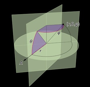
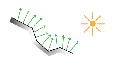
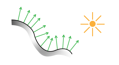
Lighting a surface using its normals.
</p>

<p>
To use normals for lighting, I have two options. The first is to do this on a geometry basis, assigning a normal to every triangle in the planet mesh. This is straightforward, but ties the quality of the shading to the level of detail in the geometry. A second, better way is to use a normal map. You stretch an image over the surface, as you would for applying textures, but instead of color, each pixel in the image represents a normal vector in 3D. Each pixel's channels (red, green, blue) are used to describe the vector's X, Y and Z values. When lighting the surface, the normal for a particular point is found by looking it up in the normal map.
</p>

<p>
The benefit of this approach is that you can stretch a high resolution normal map over low resolution geometry, often with almost no visual difference.
</p>

<p class='tc'>
<img alt='Schematic representation of surface shading with normals' src='/files/making-worlds/planet-3-normal-lighting-simple.png' />
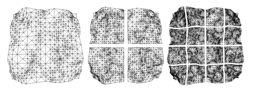
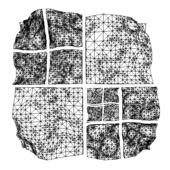
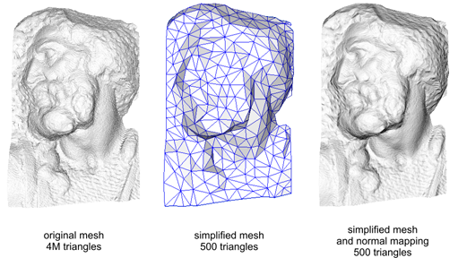
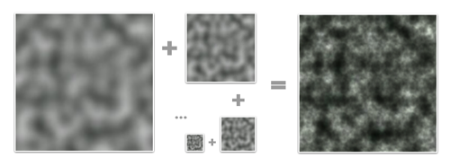
Lighting a low-resolution surface using high-resolution normals.
</p>

<p>
Here's the technique applied to a real model:
</p>

<p class='tc'>
<img alt='Normal mapping in practice' src='/files/making-worlds/planet-3-normal-mapping-3d.png' />
(<a href='http://en.wikipedia.org/wiki/File:Normal_map_example.png'>Source</a> - Creative Commons Share-alike Attribution)
</p>

<p>
Normal mapping helps keep performance up and memory usage down.
</p>

<h3>Finding Normals</h3>

<p>
So how do you generate such a normal map, or even a single normal at a single point? There are many ways, but the basic principle is usually the same. First you calculate two different vectors which are tangent to the surface at the point in question. Then you use the <a href='http://en.wikipedia.org/wiki/Cross_product'>cross product</a> to find a vector perpendicular to the two. This third vector is unique and will be the surface normal.
</p>

<p>
For triangles, you can pick any two triangle edges as vectors. In my case, the surface is described by a heightmap on a sphere, which makes things a bit trickier and requires some math.
</p>

<p>
I asked my friend <a href='http://twitter.com/mathseeker'>Djun Kim</a>, Ph.D. and teacher of mathematics at UBC for help and he recommended <a href='http://en.wikipedia.org/wiki/Calculus_on_Manifolds_(book)'>Calculus on Manifolds</a> by Michael Spivak. This deceptively small and thin book covers all the basics of calculus in a dense and compact way, and quickly became my new favorite reading material.
</p>

<h2>Differential Geometry</h2>

<p>
In this section, I'll describe the formulas needed to calculate the normals of a spherical heightmap. Unlike what I've written before, this will dive shamelessly into specifics and not eschew math. The reason I'm writing it down is because I couldn't find a complete reference online. If math scares you, this section might not be for you. Scroll down until you reach the crater, or take a detour by reading <a href='http://www.maa.org/devlin/LockhartsLament.pdf'>A Mathematician's Lament</a> by Paul Lockhart, which will enlighten you.
</p>

<p>
First, we're going to derive normals for a regular flat terrain heightmap. To start, we need to define the terrain surface. Starting with a 2D heightmap, i.e. a function <em>f(u,v)</em> of two coordinates that returns a height value, we can create a 3 dimensional surface <em>g</em>:
</p>

<p>
<img alt='Mathematical formulation of heightmapping' src='/files/making-worlds/planet-3-terrain-mapping.png' />
</p>

<p>
We can use this formal description to find tangent and normal vectors. A vector is tangent when its direction matches the slope of the surface in a particular direction. Differential math tells us that slope is found by taking the derivative. For our function of 2 variables, that means we can find tangent vectors along curves of constant <em>v</em> or constant <em>u</em>. These curves are the thin grid lines in the diagram. Actually, we can find tangents along any line, in any direction. But along <em>u</em> and <em>v</em> lines, the other variable acts like a constant, which simplifies things.
</p>

<p>
To do this, we take partial derivatives with respect to <em>u</em> (with <em>v</em> constant) and with respect to <em>v</em> (with <em>u</em> constant). The set of all partial derivatives is called the Jacobian matrix J, whose rows form the tangent vectors <b>t<sub>u</sub></b> and <b>t<sub>v</sub></b>, indicated in red and purple:
</p>

<p>
<img alt='Heightmapping, jacobian, finding normals' src='/files/making-worlds/planet-3-terrain-mapping-jacobian.png' />
</p>

<p>
The cross product of <b>t<sub>u</sub></b> and <b>t<sub>v</sub></b> gives us <b>n</b>, the surface normal.
</p>

<p>
When applied to a discrete heightmap, the function <em>f(u,v)</em> is a 2D array <em>map[u][v]</em>, and the partial derivatives at the end have to be replaced with something else. We can use <a href='http://en.wikipedia.org/wiki/Finite_difference'>finite differences</a> to approximate the slope of the surface by differencing neighbouring samples:
</p>

<p>
  <img alt='Finite differences' src='/files/making-worlds/finite-diff.png' /><br />
<img alt='Heightmapping, finite differences' src='/files/making-worlds/planet-3-terrain-mapping-finite-diff.png' />
</p>

<p>
This result and the formula for <b>n</b> are usually provided as-is in terrain mapping guides, without going through the full process of finding tangents first. However, it's important to use the Jacobian matrix formulation once you switch to spherical terrain.
</p>

<p>
<img alt='Mapping a cube to a sphere' src='/files/making-worlds/planets-1-cubemap.png' />
</p>

<p>
To make a sphere, we add an additional function <em>k</em> which warps the flat terrain into a spherical shell. Each shell is the result of warping a single face of the cubemap and covers exactly 1/6th of the sphere. In what follows, We'll only consider a single face and its shell.
</p>

<p>
We designate the intermediate pre-warp coordinates <em>(s,t,h)</em>, and the final post-warp coordinates as <em>(x,y,z)</em>:
</p>

<p>
<img alt='Mathematical formulation of spherical heightmapping' src='/files/making-worlds/planet-3-sphere-mapping.png' />
</p>

<p>
The principle behind the spherical mapping is this: first we take the vector <em>(s, t, 1)</em>, which lies in the base plane of the flat terrain. We normalize this vector by dividing it by its length <em>w</em>, which has the effect of projecting it onto the sphere: <em>(s/w, t/w, 1/w)</em> will be at unit distance from <em>(0, 0, 0)</em>. Then we multiply the resulting vector by the terrain height <em>h</em> to create the terrain on the sphere's surface, relative to its center: <em>(h&middot;s/w, h&middot;t/w, h/w)</em>
</p>

<p>
Just like with the function <em>g(u,v)</em> and <em>J(u,v)</em>, we can find the Jacobian matrix <em>J(s,t,h)</em> of <em>k(s,t,h)</em>. Because there are 3 input values for the function <em>k</em>, there are 3 tangents, along curves of varying <em>s</em> (with constant <em>t and h</em>), varying <em>t</em> (constant <em>s and h</em>) and varying <em>h</em> (constant <em>s and t</em>). The three tangents are named <b>t<sub>s</sub></b>, <b>t<sub>t</sub></b>, <b>t<sub>h</sub></b>.
</p>

<p class='tc'>
<img alt='Spherical heightmapping, jacobian.' src='/files/making-worlds/planet-3-sphere-mapping-jacobian.png' />
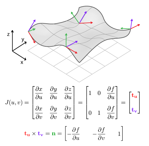
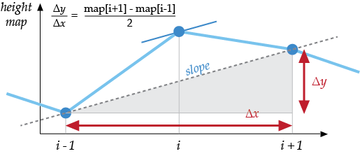
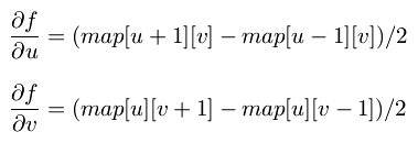
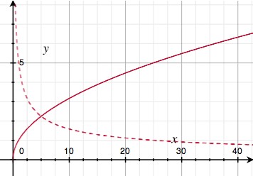
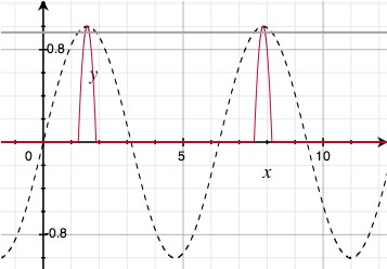
PS: If your skills at derivation are a bit rusty, remember that <a href='http://www.wolframalpha.com/input/?i=d%2Fdx+h%2Fsqrt%28x%5E2%2By%5E2%2B1%29'>Wolfram Alpha can do it for you</a>.
</p>

<p>
How does this help? The three vectors describe a local frame of reference at each point in space. Near the edges of the grid, they get more skewed and angular. We use these vectors to transform the flat frame of reference into the right shape, so we can construct a new 90 degree angle here.
</p>

<p>
In mathematical terms, we multiply the 'flat' partial derivatives by the Jacobian matrix. This is similar to the chain rule for regular derivatives, only for multiple variables.
</p>

<p>
That is, to find the partial derivatives (i.e. tangent vectors) of the final spherical terrain with respect to the original terrain coordinates <em>u</em> and <em>v</em>, we can take the flat terrain's tangents <b>t<sub>u</sub></b> and <b>t<sub>v</sub></b> and multiply them by <em>J(s,t,h)</em>. Once we have the two post-warp tangents, we take their cross product, and find the normal of the spherical terrain:
</p>

<p>
<img alt='Spherical heightmapping, jacobian.' src='/files/making-worlds/planet-3-sphere-mapping-normal.png' />
</p>

<p>
It's imporant to note that this is not the same as simply multiplying the flat terrain normal with <em>J(s,t,h)</em>. <em>J(s,t,h)</em>'s rows do not form a set of perpendicular vectors (it is not an orthogonal matrix), which means it does not preserve angles between vectors when you multiply by it. In other words, <em>J(s,t,h) * n</em>, with n the flat terrain normal, would not be perpendicular to the spherical terrain. This is why it's important to return to the basic calculus underneath, so we can get the correct, complete formula.
</p>

<p>
Thus ends the magical math adventure. If you read it all the way through, cheers!
</p>

<h2>No Wait, It is a Moon.</h2>

<p>
With the normal map in place, I can now render the planet's surface and get a realistic idea of what it looks like. To show this off, I tweaked the brush system a bit: instead of using the literal brush image (e.g. a smooth, round crater), the brush is distorted with fractal noise. It makes every application of the brush subtly different from the next, and saves me from manually drawing e.g. a hundred different craters.
</p>

<p class='tc'>
<img alt='Brush distortion.' src='/files/making-worlds/planet-3-brush-distortion.png' /><br />
Here's a side by side comparison of the original brush and a distorted version.
</p>

<p>
Currently I've only implemented one type of distortion, which lends a rocky appearance to the surface. With that in place, my engine can now generate somewhat realistic looking moon surfaces. Here's the demo:
</p>

<p>
<object height='380' width='560'><param name='movie' value='http://www.youtube.com/v/pHjyMs8tm4E&amp;hl=en&amp;fs=1&amp;' /><param name='allowFullScreen' value='true' /><param name='allowscriptaccess' value='always' /><embed allowfullscreen='true' allowscriptaccess='always' height='380' src='http://www.youtube.com/v/pHjyMs8tm4E&amp;hl=en&amp;fs=1&amp;' type='application/x-shockwave-flash' width='560' /></object>
</p>

<h3>References</h3>

<p>
The techniques I used were pioneered by people smarter and older than me, I'm just building my own little digital machine with them.
</p>

<ul>
<li><a href='http://www.cs.cmu.edu/~ajw/s2007/0251-SphericalWorlds.pdf'>Creating Spherical Worlds</a>, Maxis/Electronic Arts. (<a href='http://www.andrewwillmott.com/s2007'>source</a>).</li>
<li><a href='http://en.wikipedia.org/wiki/Calculus_on_Manifolds_(book)'>Calculus on Manifolds</a>, Michael Spivak.</li>
</ul>

</div></div>]]></content>
  </entry>
  
  <entry>
    <title type="html"><![CDATA[Making Worlds 2 - Scaling Heights]]></title>
    <link href="http://acko.net/blog/making-worlds-2-scaling-heights/"/>
    <updated>2009-08-31T00:00:00-07:00</updated>
    <id>http://acko.net/blog/making-worlds-2-scaling-heights</id>
    <content type="html"><![CDATA[<div class='g8 i2 first'><div class='pad'>
<h1>Making Worlds 2 - Scaling Heights</h1>

<p>Last time, I had a working, smooth sphere mesh. The next step is to create terrain.
</p>

<h2>Scale</h2>

<p>
Though my goal is to render at a huge range of scales, I'm going to focus on views from space first. That strongly limits how much detail I need to store and render. Aside from being a good initial sandbox in terms of content generation, it also means I can comfortably keep using my current code, which doesn't do any sophisticated memory or resource management yet. I'd much rather work on getting something interesting up first rather than work on invisible infrastructure.
</p>

<p>
That said, this is not necessarily a limitation. The interesting thing about procedural content is that every generator you build can be combined with many others, including a copy of itself. In the case of terrain, there are definite fractal properties, like self-similarity at different levels of scale. This means that once I've generated the lowest resolution terrain, I can generate smaller scale variations and combine them with the larger levels for more detail. This can be repeated indefinitely and is only limited by the amount of memory available.
</p>

<p class='tc'><img alt='Example of Perlin Noise' src='/files/making-worlds/planet-2-perlin-noise.png' />
<a href='http://en.wikipedia.org/wiki/Perlin_noise'>Perlin Noise</a> is a celebrated classic procedural algorithm,<br />
often used as a fractal generator.
</p>

<h2>Height</h2>
<p>
To build terrain, I need to create heightmaps for all 6 cube faces. Shamelessly stealing more ideas from Spore, I'm doing this on the GPU instead of the CPU, for speed. The GPU normally processes colored pixels, but there's no reason why you can't bind a heightmap's contents as a grayscale (one channel) image and 'draw' into it. As long I build my terrain using simple, repeated drawing operations, this will run incredibly fast.
</p>

<p>
In this case, I'm stamping various brushes onto the sphere's surface to create bumps and pits. Each brush is a regular PNG image which is projected onto the surface around a particular point. The luminance of the brush's pixels determines whether to raise or lower terrain and by how much.
</p>

<p class='tc'>
<img alt='Brushes from Spore' src='/files/making-worlds/planet-2-spore-brushes.png' /><br />
Three example brushes from Spore. (<a href='http://www.cs.cmu.edu/~ajw/s2007/0251-SphericalWorlds.pdf'>source</a>)
</p>

<p>
However, while the brushes need to appear seamless on the final sphere, the drawing area consists only of the straight, square set of cube map faces. It might seem tricky to make this work so that the terrain appears undistorted on the curved sphere grid, but in fact, this distortion is neatly compensated for by good old perspective. All I need to do is set up a virtual scene in 3D, where the brushes are actual shapes hovering around the origin and facing the center. Then, I place a camera in the middle and take a snapshot both ways along each of the main X, Y and Z directions with a perfect 90 degree field of view. The resulting 6 images can then be tiled to form a distortion-free cube map.
</p>

<p>
<img alt='Rendering a cubemap' src='/files/making-worlds/planet-2-cubemap-rendering.png' />
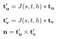
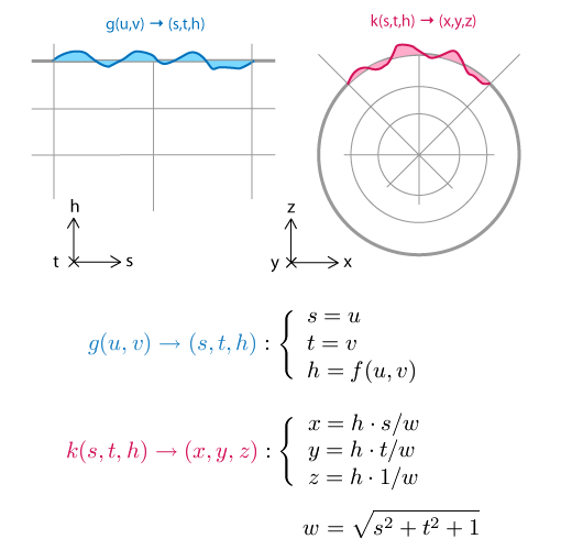
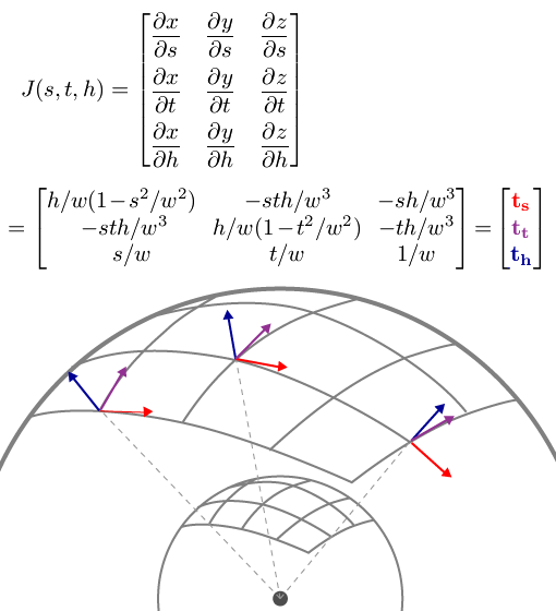
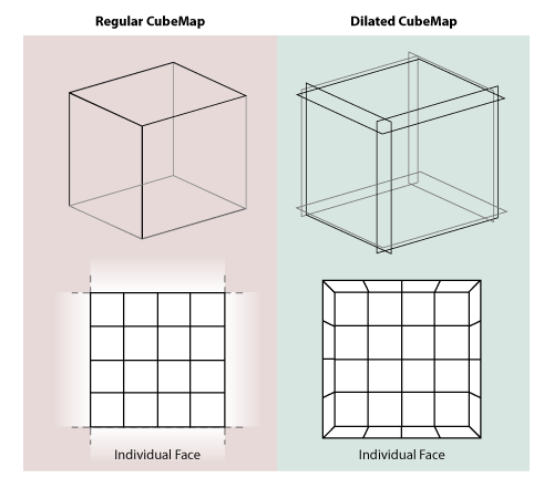
Rendering two different cube map faces. The red area is the camera's viewing cone/pyramid, which extends out to infinity.
</p>

<p>
To get started I built a very simple prototype, using Ogre's scene manager facilities. I'm starting with just a simple, smooth crater/dent brush. I generate all 6 faces in sequence on the GPU, pull the images back to the CPU to create the actual mesh, and push the resulting chunks of geometry into GPU memory. This is only done once at the beginning, although the possibility is there to implement live updates as well.
</p>

<p>
Here's a demo showing a planet and the brushes that created it, hovering over the surface. I haven't implemented any shading yet, so I have to toggle back and forth to wireframe mode so you can see the dents made by the brushes:
</p>

<p>
<object height='380' width='560'><param name='movie' value='http://www.youtube.com/v/AX_LiBnZJTc&amp;hl=en&amp;fs=1&amp;' /><param name='allowFullScreen' value='true' /><param name='allowscriptaccess' value='always' /><embed allowfullscreen='true' allowscriptaccess='always' height='380' src='http://www.youtube.com/v/AX_LiBnZJTc&amp;hl=en&amp;fs=1&amp;' type='application/x-shockwave-flash' width='560' /></object>
</p>

<p>
The cubemap for this 'planet' looks like this when flattened. You can see that I haven't actually implemented real terrain carving, because brushes cause sharp edges when they overlap:
</p>

<p>
<img alt='Generated planet cubemap' src='/files/making-worlds/planet-2-cubemap.png' />
</p>

<p>
The narrow dent on the left gets distorted and angular where it crosses the cube edge. This is a normal consequence of the cubemapping, as it looks perfectly normal when mapped onto the sphere in the video.
</p>

<h2>Engine Tweaks</h2>

<p>
The demo above also incorporates a couple of engine improvements. With a real heightmap in place, I can implement real level-of-detail selection. That means the resolution of any terrain tile is decided based on how much detail would be lost if a simpler tile was used. The flatter a tile, the less detail is necessary. This ensures complex geometry is used only on those sections that really need it. This is great for visual fidelity, but causes a lot of geometry to pop up if sharp ridges are present in the terrain. In this case, my rendering engine was happily trying to push 700k triangles through the GPU per frame. While even my laptop GPU can actually do that at pretty smooth frame rates nowadays, some optimizations are in order to give me some breathing room.
</p>

<p>
The culprit was that I wasn't really doing any early removal of geometry that was hidden or otherwise out of frame. To fix that, I now do visibility checks together with the level-of-detail selection. First it checks if a chunk is over the horizon or not before considering it for selection. This is easy to calculate and eliminates a lot of unnecessary drawing, especially when looking straight down. If that first visibility check passes, I perform a tighter check using the camera's viewing cone. With these two measures in place, I'm only averaging about 50,000-100,000 triangles visible per frame, with room for more optimization. These optimizations only remove geometry that's already off screen, so there is no visual difference.
</p>

<h3>Cubemap Seams and Dilation</h3>

<p>
When rendering into cube maps, each side is rendered independently. In theory each face should match perfectly with adjacent ones due to the way they've been created. In practice however, slight mismatches can occur due to rounding errors at the edges, creating seams. This can be fixed by explicitly copying one pixel-wide edges from one face into the adjacent ones, until they all match up.
</p>

<p>
The next big step is to start shading the surface, but in order to do that I need to be able to run filters on the cube map. Specifically, I need to be able to compare neighbouring height samples anywhere on the surface. In the straight forward cubemap scenario this is non-trivial, because neighbouring samples at the edges need to be fetched from different cube faces at different orientations in space.
</p>

<p>
I decided to implement something I call 'dilated cubemaps'. I've never really heard this described formally, though I doubt it's never been thought of before:
</p>

<p>
<img alt='A dilated cubemap' src='/files/making-worlds/planet-2-dilated-cubemap.png' />
</p>

<p>
Instead of every face neatly matching with the next, I dilate the cube faces so they stick through eachother. At the same time, I use a larger texture size to compensate, and I adjust the field-of-view of the rendering camera to match. If done right, the resulting cubemap is a pixel-perfect expanded version of the undilated map.
</p>

<p>
The dilated cubemap provides reliable neighbouring samples for all samples in the original cube map up to a distance as wide as the new border. Unlike regular cubemap wrapping, the dilated regions are distorted to conform to the current face's grid. This matches the real change in grid direction that occurs on the final sphere mesh and lets you sample exactly across cube map edges.
</p>

<p>
I played with the cubemap dilation because I was thinking of some complicated filters to run that require regular grids (like CFD). But in retrospect, I probably don't need the exact spacing of sample points at the edges for this, so regular undilated cubemapping will probably do. Still, it's good to have around, and certainly was an interesting exercise in pixel-exact rendering.
</p>

<h2>What Next?</h2>

<p>
With basic heightmap generation in place, I can now start putting in some 'tech artist' time to play with various brushes and drawing behaviour. Lighting and shading is another big one and should provide a massive improvement to the visuals.
</p>

<p>
Right now I've taken a week between postings, though it remains to be seen whether I can maintain that. Creating these blog entries is turning into a pretty time consuming endeavour, especially as I get into territory where I have to make my own diagrams and illustrations.
</p>

<h3>References</h3>

<p>
The techniques I used were pioneered by people smarter and older than me, I'm just building my own little digital machine with them.
</p>

<ul>
<li><a href='http://www.cs.cmu.edu/~ajw/s2007/0251-SphericalWorlds.pdf'>Creating Spherical Worlds</a>, Maxis/Electronic Arts. (<a href='http://www.andrewwillmott.com/s2007'>source</a>).</li>
<li><a href='http://en.wikipedia.org/wiki/Ken_Perlin'>Ken Perlin</a>, who invented a lot of this stuff.</li>
</ul>

</div></div>]]></content>
  </entry>
  
  <entry>
    <title type="html"><![CDATA[Making Worlds 1 - Of Spheres and Cubes]]></title>
    <link href="http://acko.net/blog/making-worlds-1-of-spheres-and-cubes/"/>
    <updated>2009-08-23T00:00:00-07:00</updated>
    <id>http://acko.net/blog/making-worlds-1-of-spheres-and-cubes</id>
    <content type="html"><![CDATA[<div class='g8 i2 first'><div class='pad'>
  
<h1>Making Worlds 1 - Of Spheres and Cubes</h1><p>Let's start making some planets! Now, while this started as a random idea kind of project, it was clear from the start that I'd actually need to do a lot of homework for this. Before I could get anywhere, I needed to define exactly what I was aiming for.
</p>

<p>
The first step in this was to shop around for some inspirational art and reference pictures. While there is plenty space art to be found online, in this case, nothing can substitute for the real thing. So I focused my search on real pictures, both of landscapes (terran or otherwise) as well as from space. I found classy shots like these:
</p>

</div></div><div class='g3 m1'><div class='pad'>
  
  <p>
    <a href='http://en.wikipedia.org/wiki/Enceladus_(moon)'><img alt='The moon Enceladus' class='inline' src='/files/making-worlds/planets-1-enceladus.jpg' /></a>
  </p>

</div></div><div class='g6'><div class='pad'>

<p class='flat'>
  <img alt='Landscape' src='/files/making-worlds/planets-1-landscape.jpg' />
</p>

</div></div><div class='g3 m1'><div class='pad'>
  
  <p>
    <a href='http://en.wikipedia.org/wiki/Mars'><img alt='Mars' class='inline' src='/files/making-worlds/planets-1-mars.png' /></a>
  </p>

</div></div><div class='g8 i2'><div class='pad'>
<p>
Hopefully I'll be able to render something similar in a while. At the same time, I eagerly devoured any paper I could find on rendering techniques from the past decade, some intended for real-time rendering, some old enough to be real-time today.
<!--break-->
Out of all this, I quickly settled on my goals:
<ul>
  <li>Represent spherical or lumpy heavenly bodies from asteroids to suns.</li>
  <li>With realistic looking topography and features.</li>
  <li>Viewable across all scales from surface to space.</li>
  <li>At flight-simulator levels of detail.</li>
  <li>Rendered with convincing atmosphere, water, clouds, haze.</li>
</ul>
</p>

<p>
For most of these points, I found one or more papers describing a useful technique I could use or adapt. At the same time, there are still plenty of unknowns I'll need to figure out along the way, not to mention significant amounts of fudging and experimentation.
</p>

<h3>The Spherical Grid</h3>

<p>
To get started I needed to build some geometry, and to do that I needed to figure out what geometry I should use. After reviewing some options, I quickly settled on a regular spherical displacement map (AKA a heightmap). That is, starting with a smooth sphere, move every surface point up or down, perpendicular to the surface, to create terrain on the surface.
</p>

<p>
If these vertical displacements are very small compared to the sphere radius, this can represent the surface of a typical planet (like Earth) at the levels of detail I'm looking for. If the displacements are of the same order as the sphere radius, you can deform it into very irregular potato-like shapes. The only thing heightmaps can't do is caves, tunnels, overhang and other kinds of holes, which is fine for now.
</p>

<p>
The big question is, how should the spherical surface be divided up and represented? With a sphere, this is not an easy question, because there is no single obvious way to divide a spherical surface into regular sections or grids. Various techniques exist, each with their own benefits and specific use cases, and I spent quite some time looking into them. Here's a comparison between four different tesselations:
</p>

<p class='tr'>
<img alt='Different tesselations of a sphere' src='/files/making-worlds/planets-1-sphere-tesselations.png' /><small><a href='http://adsabs.harvard.edu/cgi-bin/nph-bib_query?bibcode=2005ApJ...622..759G'>Source</a></small>
</p>

<p>
Note that the tesselation labeled ECP is just the regular geographic latitude-longitude grid.
</p>

<p>
The main features I was looking for were speed and simplicity, so I settled on the 'quadcube'. This is where you start with a cube whose faces have been divided into regular grids, and project every surface point out from the middle to an enclosing sphere. This results in a perfectly smooth sphere, built out of 6 identical round shells with curved edges. This arrangement is better known as the 'cube map' and often used for storing arbitrary 360 degree panorama views.
</p>

<p>
Here's a cube and its spherical projection:
</p>

<p>
<img alt='Mapping a cube to a sphere' src='/files/making-worlds/planets-1-cubemap.png' />
<small>The projected cube edges are indicated in red. Note that the resulting sphere is perfectly smooth and round, even though the grid has a bulgy appearance.</small>
</p>

<p>
Cube maps are great, because they are very easy to calculate and do not require complicated trigonometry. In reverse, mapping arbitrary spherical points back onto the cube is even simpler and in fact natively supported by GPUs as a texture mapping feature.
</p>

<p>
This is important, because I'll be generating the surface terrain and texture dynamically and will need to index and access each surface 'pixel' efficiently. Using a cube map, I simply identify the corresponding face, and then index it using x/y coordinates on the face's grid.
</p>

<p>
The downside of cube maps is that the distance and area between points varies along the grid, which makes it harder to perform certain operations on a surface equally. However, these area distortions are much smaller than e.g. a lat-long grid, where the grid spacing actually approaches zero near the poles. Even more, the distortions made by a cube map are the exact opposite of those you get with a regular perspective projection. This makes it easy to render into cube maps, which will be useful for texture generation.
</p>

<h3>Level of Detail</h3>

<p>
There's another reason I picked the cube map approach, and that has to do with the level of detail requirements. My goal is to make a planet that can be viewed from the ground, the air as well as from space. It would be incredibly slow to always render everything at maximum detail, so I need to adaptively add and remove detail as the viewer gets closer to the surface.
</p>

<p>
However, increasing the level of detail uniformly across the entire sphere is not enough, because I only want to render detail where the viewer will see it. To a viewer on the ground, most of the planet is hidden by the horizon, and the engine should be able to effectively cut away the unseen pieces, so no wasteful processing takes place.
</p>

<p>
It is here that I get a huge benefit from the cube map layout of the sphere, because it lets me apply the well-researched realm of grid-based flat terrain rendering with only minor adjustments. Specifically, I am using a 'chunked LOD' approach. Every face of the cube map becomes a quadtree, with each level splitting four ways to form the next level with more detail:
</p>

<p class='tr'>
<img alt='Quadtree terrain' src='/files/making-worlds/planets-1-quadtree.png' /><small><a href='http://tulrich.com/geekstuff/sig-notes.pdf'>Source</a></small>
</p>

<p>
The chunks for the various levels of detail are all loaded into GPU memory, ready to be accessed at any time. When the terrain has to be rendered, the engine walks down the quad-tree, determines the appropriate level-of-detail for each section, and outputs the list of chunks to be rendered for a particular frame. Then, the GPU does its work, blasting through each chunk at a blistering pace, leaving the CPU to do other things.
</p>

<p>
<img alt='Configuration of chunks to render' src='/files/making-worlds/planet-lod-tree.png' />
</p>

<p>
Because all the data is already in memory, changing the level of detail just means rendering a different set of chunks. Each chunk has the same geometrical complexity, and performance is directly proportional to how many are rendered on screen. More detail means more chunks, but that usually also means you can cut away pieces of the terrain that are far away.
</p>

<p>
The chunked approach is also very easy to work with, because there is no data dependency between the different chunks. Each chunk has a copy of its own vertex data, which means individual chunks can be paged in and out of GPU memory at will. This is important for keeping memory usage down while still being able to scale to massive sizes.
</p>

<h3>Putting It All Together</h3>

<p>
At this point, I have all the pieces in place to render an adaptive sphere mesh. This is what it looks like (sorry, the video capture is a bit jerky):
</p>

<p>
<object height='380' width='560'><param name='movie' value='http://www.youtube.com/v/LxZhWrSmrOY&amp;hl=en&amp;fs=1&amp;' /><param name='allowFullScreen' value='true' /><param name='allowscriptaccess' value='always' /><embed allowfullscreen='true' allowscriptaccess='always' height='380' src='http://www.youtube.com/v/LxZhWrSmrOY&amp;hl=en&amp;fs=1&amp;' type='application/x-shockwave-flash' width='560' /></object>
</p>

<p>
The detail increases as the camera gets closer to the sphere and shifts around the surface as it moves.
</p>

<p>
Far from being a little coding experiment, it actually took me quite some time to get to this point, because I was learning OGRE, sharpening my C++ skills, as well as researching the techniques to use.
</p>

<p>
The next step is to look at generating heightmaps and textures for the surface.
</p>

<h3>References</h3>

<p>
The techniques I used were pioneered by people smarter and older than me, I'm just building my own little digital machine with them.
</p>

<ul>
<li><a href='http://www.cs.cmu.edu/~ajw/s2007/0251-SphericalWorlds.pdf'>Creating Spherical Worlds</a>, Maxis/Electronic Arts. (<a href='http://www.andrewwillmott.com/s2007'>source</a>).</li>
<li><a href='http://tulrich.com/geekstuff/sig-notes.pdf'>Rendering Massive Terrains using Chunked Level of Detail Control</a>, Thatcher Ulrich. (<a href='http://tulrich.com/geekstuff/chunklod.html'>source</a>)</li>
</ul>

</div></div>]]></content>
  </entry>
  
  <entry>
    <title type="html"><![CDATA[Making Worlds: Introduction]]></title>
    <link href="http://acko.net/blog/making-worlds-introduction/"/>
    <updated>2009-08-22T00:00:00-07:00</updated>
    <id>http://acko.net/blog/making-worlds-introduction</id>
    <content type="html"><![CDATA[<div class='g8 i2 first'><div class='pad'><h1>Making Worlds: Introduction</h1><p>For the past year or so I've been reacquainting myself with an old friend: C++.
</p>

<p>
More specifically, I've been exploring graphics programming again, this time with the luxurious flexibility of the modern GPU at my fingertips. To get me started, I shopped around for an open source engine to play with. After trying Irrlicht and finding its promises to be a bit lacking, <a href='http://www.ogre3d.org'>Ogre</a> turned out to be a really good choice. Though its architecture is a bit intimidating at first, it is all the more sound. More importantly, it seems to have a relatively healthy open-source community around it.
</p>

<p>
So with Ogre as my weapon of choice, I've started a new project: Making Worlds. More specifically, I want to procedurally generate a 3D planet, viewable from outer space as well as the ground (at flight-sim levels of detail), which can be rendered real-time on recent graphics hardware.
</p>

<p>
Why? Because I really like procedural content generation. It's an odd discipline where anything goes, and techniques from across mathematics, engineering and physics are applied. Then, you add a good dose of creativity and artistic sense, and perhaps mix in some real-world data too, until you find something that looks right.
</p>

<p>
Plus, far from being an exercise in pointlessness, procedural content is <a href='http://www.escapistmagazine.com/articles/view/columns/experienced-points/6418-The-Future-is-Procedural'>gaining in popularity</a>, especially for video games.
</p>

<p>
So, in the style of Shamus Young's excellent <a href='http://www.shamusyoung.com/twentysidedtale/?p=2940'>Procedural city</a> series, I'm going to start blogging about Making Planets. Unlike him however, I'm not going to adhere to a strict schedule.
</p>

<p>
<img alt='Geosphere' src='/files/making-worlds/geosphere.png' />
</p>

<p>
Here's a teaser for the first installment.
</p>

</div></div>]]></content>
  </entry>
  
  <entry>
    <title type="html"><![CDATA[JavaScript audio synthesis with HTML 5]]></title>
    <link href="http://acko.net/blog/javascript-audio-synthesis-with-html-5/"/>
    <updated>2009-08-12T00:00:00-07:00</updated>
    <id>http://acko.net/blog/javascript-audio-synthesis-with-html-5</id>
    <content type="html"><![CDATA[<div class='g8 i2 first'><div class='pad'><h1>JavaScript audio synthesis with HTML 5</h1>
  
<aside class='r'><a href='http://acko.net/files/audiosynth/index.html'><img alt='Audio wave' src='/files/audiosynth/audio.png' /></a></aside>

<p>
  HTML5 gives us a couple new toys to play with, such as &lt;AUDIO&gt; and &lt;VIDEO&gt; tags. On the visual side, we've already seen <a href='https://developer.mozilla.org/samples/video/chroma-key/index.xhtml'>live green-screening</a> with Canvas and JS, and in terms of audio there's been several JS <a href='http://www.randomthink.net/labs/html5drums/'>drum machines</a> already. But the question I was interested in was: can you use JavaScript to stream live data into these media tags?
</p>

<p>
Enter the <a href='http://acko.net/files/audiosynth/index.html'>JavaScript audio synth</a>. It generates a handful of samples using very basic time-domain synthesis, wraps them up in a WAVE file header and embeds them in &lt;AUDIO&gt; tags using base64-encoded data URIs. Each sample is then triggered using timers to play the drum pattern. It's quite simple to do and runs fast enough in HTML5 capable browsers to be unnoticeable. Yes, it sounds tinny, but that's just because I'm too lazy to design proper filters for toys like this.
<!--break-->
Unfortunately, while the synthesis is fast enough to run real-time, you can't actually use it for a full live audio stream, as there is no way to queue up chunks of synthesized audio for seamless playback. I tried triggering multiple &lt;AUDIO&gt; tags in parallel to address this, but that didn't work either.
</p>

<p>
My final attempt was to generate tons of periodic audio loops only a couple of ms long, and to play them back with looping turned on while altering each tag's volume in real time, hence doing a sort of additive wavetable synthesis. Unfortunately, looping is not a fully supported feature, and the only browser I found that does it (Safari) doesn't loop seamlessly at all.
</p>

<p>
All in all, my first brush with the &lt;AUDIO&gt; tag was a major disappointment. The &lt;VIDEO&gt; tag's high-level approach leads to similar limitations, but they are offset by the flexibility and power of the &lt;CANVAS&gt; tag. Unfortunately, there is no 'audio canvas' to solve similar problems with audio.
</p>

</div></div>]]></content>
  </entry>
  
  <entry>
    <title type="html"><![CDATA[Sadly, undeniably true]]></title>
    <link href="http://acko.net/blog/sadly-undeniably-true/"/>
    <updated>2008-01-15T00:00:00-08:00</updated>
    <id>http://acko.net/blog/sadly-undeniably-true</id>
    <content type="html"><![CDATA[<div class='g8 i2 first'><div class='pad'><h1>Sadly, undeniably true</h1><p>... at least the last bit:
</p>

<p>
<blockquote>“when the world ends, the only things left will be cockroaches, rats, Keith Richards, and mangled text that has been escaped one-too-many or one-too-few times” — <a href='
http://web.archive.org/web/20040812224831/http://blogs.law.harvard.edu/crimson1/discuss/msgReader$1714?mode=day'>Dave Walker</a></blockquote>
</p>

<p>
(found this little gem via <a href='http://www.intertwingly.net/blog/2007/12/10/REXML-and-Mangled-Text'>Sam Ruby</a>)</p></div></div>]]></content>
  </entry>
  
  <entry>
    <title type="html"><![CDATA[Cocoa, Lemons and Geeks]]></title>
    <link href="http://acko.net/blog/cocoa-lemons-and-geeks/"/>
    <updated>2006-04-22T00:00:00-07:00</updated>
    <id>http://acko.net/blog/cocoa-lemons-and-geeks</id>
    <content type="html"><![CDATA[<div class='g8 i2 first'><div class='pad'><h1>Cocoa, Lemons and Geeks</h1><p>Greetings from Amsterdam. I'm here for the second day of <a href='https://cocoadevhouse.pbwiki.com/CocoaDevHouseAmsterdam'>CocoaDevHouse</a>! About 20 geeks have been camping out in the Post C.S. building to gather, discuss, develop and generally have fun.
</p>

<p>
I've mainly come to work on my first Cocoa app (<em>LemonJuice</em>) and benefit from the expertise of people who actually know the API ;). I've gone from "typing a bunch of random crap" to "doing cool stuff with ridiculously small amounts of code". Cocoa is definitely interesting, and far more powerful than the Windows API I've used for a couple of years.
</p>

<p>
More details inside...
<!--break-->
</p>

<p>
The application I've been coding is essentially, a WebKit based Terminal. I dislike the fact that a typical bash session in a GUI terminal is not a very consistent experience. For example, bash does not understand the normal home/end keys. And because you're not typing in a normal textbox, you can't select text by holding shift, have spell checking, and non-destructive autocompletion. What's also important to me is that the typical shell command now outputs a very ugly, very UNIXy stream of text. Whereas usually, that information is quite structured (a list of files, a list of key/value pairs, a timestamp, a media file, ...). Files and hyperlinks should be clickable. Tables should be sortable. Etc. etc.
</p>

<p>
So, I want to use WebKit (the engine behind Safari) to make a Terminal that outputs nicey styled HTML. A directory listing would emerge as a nicely formatted table with icons, for example. But you could just as well pipe that list into another application, without losing the structure (sort of what Microsoft's Monad is supposed to be like).
</p>

<p>
<img alt='LemonJuice' src='/files/lemonjuice/lemon128.png' style='float: left; padding: 0px 15px 15px 0px;' /> Of course, I have no clue if I can build such a thing. I'm essentially going blind now, coding until I have a good prototype ;). So far I've got "cd", "ls" and "quit" working. Still, most of the work now has been trying to figure out how I can achieve things in a way that is Cocoa-ish and clean. At least I'm having fun...
</p>

<p>
<strong>Current prototype:</strong>
<div style='align: center;'><img alt='' src='/files/lemonjuice/lemonjuice.png' style='border: 1px solid #c0c0c0;' /></div></p></div></div>]]></content>
  </entry>
  
  <entry>
    <title type="html"><![CDATA[Handy Drupal Core Development]]></title>
    <link href="http://acko.net/blog/handy-drupal-core-development/"/>
    <updated>2006-04-12T00:00:00-07:00</updated>
    <id>http://acko.net/blog/handy-drupal-core-development</id>
    <content type="html"><![CDATA[<div class='g8 i2 first'><div class='pad'><h1>Handy Drupal Core Development</h1><p>Some quick tips for better productivity when developing Drupal core:
<ul>
<li>Alias your editor to <code>e</code>. If you use a GUI editor see if it comes with a command-line shortcut to use. TextMate by default has <code>mate</code>. Not nearly short enough ;).</li>
<li>Set up a <code>d</code> command to perform diffs. I use the following:
<code>#!/bin/bash<br />
cvs&nbsp;diff&nbsp;-u&nbsp;-N&nbsp;-F^f&nbsp;.&nbsp;|&nbsp;grep&nbsp;-v&nbsp;-e&nbsp;^\?&nbsp;&gt;&nbsp;$1.patch<br />
e&nbsp;$1.patch</code>
This opens up my editor afterwards so I can review the patch before submitting. The <code>grep</code> strips out unnecessary junk (unknown files).</li>
<li>Set up a <code>p</code> command to apply patches. I use the following:
<code>#!/bin/bash<br />
wget&nbsp;-O&nbsp;-&nbsp;$1&nbsp;|&nbsp;patch&nbsp;-p0</code>
This will take a patch URL and apply it locally.</li>
</ul>
</p>

<p>
Anyone else have anymore ideas?
</p></div></div>]]></content>
  </entry>
  
  <entry>
    <title type="html"><![CDATA[The Cocoa Journey Begins]]></title>
    <link href="http://acko.net/blog/the-cocoa-journey-begins/"/>
    <updated>2006-04-09T00:00:00-07:00</updated>
    <id>http://acko.net/blog/the-cocoa-journey-begins</id>
    <content type="html"><![CDATA[<div class='g8 i2 first'><div class='pad'><h1>The Cocoa Journey Begins</h1><p>Life is full of nice surprises.
</p>

<p>
Last week I decided I would start learning <a href='http://developer.apple.com/cocoa/'>Cocoa</a> (for the unaware, that's one of the two APIs/Frameworks for creating applications for OS X). Partially, because I have some cool ideas I want to try out. Mostly, because I want to be able to make applications that are <em>just as nice</em> as all those other sweet programs I've come to depend on since I <a href='http://www.acko.net/blog/new-powerbook'>joined the cult</a>.
</p>

<p>
So when I was doing some undirected browsing yesterday I found out that <a href='http://www.an9.org/'>Andy 'Termie' Smith</a> is helping organise <a href='https://cocoadevhouse.pbwiki.com/CocoaDevHouseAmsterdam'>CocoaDevHouse Amsterdam</a>. I'm definitely going to go there. It'll be interesting to be a total newbie at a geek event for once ;).
</p>

<p>
It's only 2.5 hours by regular train, and I have a laptop and a copy of the Apple Developer Docs to keep me occupied on the way. Interesting for those of you on the other side of the pond: the typical Belgian (and generally Western-European) mentality would consider such a trip a significant adventure. That's what happens when everyone is so focused on their own little patch of land. For me, it's now just 'popping over'. I might be back later for <a href='http://barcamp.org/BarCampAmsterdamII'>Barcamp Amsterdam II</a> too.</p></div></div>]]></content>
  </entry>
  
  <entry>
    <title type="html"><![CDATA[Degradable Javascript Widget Fun]]></title>
    <link href="http://acko.net/blog/degradable-javascript-widget-fun/"/>
    <updated>2005-10-22T00:00:00-07:00</updated>
    <id>http://acko.net/blog/degradable-javascript-widget-fun</id>
    <content type="html"><![CDATA[<div class='g8 i2 first'><div class='pad'><h1>Degradable Javascript Widget Fun</h1><p>At BarCamp Amsterdam, I worked with <a href='http://www.daemon.co.za'>Adrian Rossouw</a> on a UI for styling a website. The result is a <a href='http://www.acko.net/demo/picker'>pretty cool color picker</a> like in Gimp or Photoshop, but without Flash or Java. It just uses Javascript, CSS and transparent PNGs. It degrades to regular textboxes where you type/paste an HTML color code.
</p>

<p>
A bit later, Chris Messina suggested a slider control. Not much later, it was finished. It degrades to a plain select box, which is where the slider values are taken from. Its main purpose is to be used to select between options, and not for arbitrary continuous ranges.
</p>

<p>
These will soon be coming to a <a href='http://drupal.org/'>Drupal</a> site near you after some more polishing and bug testing. Whether they will be used in Drupal 4.7 remains to be seen (though I can already think of a few spots where they would be useful).
</p>

<p>
Yay for open-source developer cross pollination :).
</p></div></div>]]></content>
  </entry>
  
  <entry>
    <title type="html"><![CDATA[Summer of Code - Ajax Functionality for Drupal]]></title>
    <link href="http://acko.net/blog/summer-of-code-ajax-functionality-for-drupal/"/>
    <updated>2005-09-01T00:00:00-07:00</updated>
    <id>http://acko.net/blog/summer-of-code-ajax-functionality-for-drupal</id>
    <content type="html"><![CDATA[<div class='g8 i2 first'><div class='pad'><h1>Summer of Code - Ajax Functionality for Drupal</h1><aside class='r m1'><img alt='' src='/files/soc2006/soc.png' /></aside><p>
This last summer I was sponsored by Google as part of their <a href='http://code.google.com/summerofcode.html'>Summer of Code</a> progam to work on Drupal. My goal was to introduce various <a href='http://en.wikipedia.org/wiki/AJAX' title='Asynchronous JavaScript and XML'>AJAX</a> functionalities to <a href='http://www.drupal.org/'>Drupal</a>.
</p>

<p>
The official project description was:
<blockquote><em>"Drupal has recently begun to find meaningful ways to introduce AJAX functionality with the goal of improving the user experience. Work with Drupal's usability experts to identify the next steps and help implement new dynamic functions based on interaction with the XMLHttpRequest object."</em></blockquote>
</p>

<p>
I focused on the following Ajax-powered features:
<ul>
<li><strong>Inline Editing of posts</strong>: Though I built a working prototype module, I decided not to develop this feature further because it is not flexible enough to work as a generic Drupal module. It would break on too many configurations and has limited usefulness anyhow.</li>
<li><a href='http://drupal.org/node/28483'>Uploading of files</a>: allows you to attach files to Drupal nodes (with upload.module) without having to reload the page.</li>
<li><a href='http://drupal.org/node/30150'>Sorting tables inside a page</a>: this changes the sort order of a table without reloading the entire page. It is not client-side sorting as you'd expect at first sight: because most tables in Drupal are spread across multiple pages, client-side sorting is not very useful.</li>
<li><strong>Switching between multiple pages</strong>: this was implemented on top of the sorting functionality, and only works on paged tables (this covers most of the useful pagers though).</li>
<li><a href='http://acko.net/yay-progress'>Progressbar widget</a>: a typical progressbar that fetches the status from the server through Ajax.</li>
</ul>
</p>

<p>
The resulting code can be found in <a href='http://cvs.drupal.org/viewcvs/drupal/contributions/sandbox/unconed/soc/'>my sandbox</a> in the Drupal contributions repository. Note however that most of the code is in patches against the (rapidly changing) Drupal HEAD, so they are likely to go out of date soon.
</p>

<p>
The file uploader is now already part of the Drupal HEAD, and at least the tablesorter is sitting in the patch queue being reviewed. I will try and keep them up to date.
</p>

<p>
A big thanks goes to Google for organising the Summer of Code!</p></div></div>]]></content>
  </entry>
  
  <entry>
    <title type="html"><![CDATA[PHP, Unicode and ostriches.]]></title>
    <link href="http://acko.net/blog/php-unicode-and-ostriches/"/>
    <updated>2005-03-25T00:00:00-08:00</updated>
    <id>http://acko.net/blog/php-unicode-and-ostriches</id>
    <content type="html"><![CDATA[<div class='g8 i2 first'><div class='pad'><h1>PHP, Unicode and ostriches.</h1><p><em>Update: I've written a <a href='/blog/unicode-in-php'>follow-up post</a> that describes how I would like PHP's encoding support to be.</em>
</p>

<p>
As the resident encoding geek on the <a href='http://www.drupal.org/'>Drupal</a> team, it's usually my job to make sure Drupal handles encodings and Unicode correctly. I don't mind doing this, but PHP doesn't exactly make it easy. With the new search.module for Drupal 4.6 being Unicode-aware, this has become very obvious, as we've had to bump up the minimum required version of PHP to 4.3.3. The UTF-8 support in the Perl-compatible regular expressions in PHP 4.3.2 and earlier is completely broken. And now I've had a bug report about someone on PHP 4.3.8 who still had problems getting it to work.
</p>

<p>
I don't know why exactly, but as far as encodings go PHP is still in the stone-age. This is odd, as you'd expect a web-oriented scripting language to have excellent support for sharing and exchanging textual information. There is a multi-byte string extension available, but it's not available on 90% of PHP hosts out there, and it's more of a black-box library anyway: it does not present you your strings as Unicode character codepoints, but still as an array of bytes. Furthermore, if you actually enable the mbstring overrides, you lose the ability to work with bytes at will. Apparently, the PHP team still hasn't figured out that bytes and characters are not the same. The other extensions which deal with encodings (iconv, recode) are also unavailable on the majority of PHP installs out there.
</p>

<p>
This means that if you want to make a PHP application which supports any language <em>and</em> runs on the average PHP host out there, that there's only one option: use UTF-8 internally, and write your own functions for string truncation, email header encoding, validation, etc. Using UTF-8 ensures that you only have one encoding to worry about and because it's Unicode it is guaranteed to be able to represent any language. Of course, you will no longer be able to do something simple as upper/lowercasing a string, as these PHP functions don't take UTF-8 at all.
</p>

<p>
What PHP needs is Unicode string support in the core, along with a good library of useful functions for handling the very large Unicode character range efficiently. ASP, Perl, Python, Java all have it... for me, it's the only thing that would've made PHP5 worth to upgrade to.
</p>

<p>
It's as if the entire PHP team has stuck their head in the ground, hoping that all this Unicode stuff will somehow blow over. It won't.
</p></div></div>]]></content>
  </entry>
  
  <entry>
    <title type="html"><![CDATA[Sprankle Character Map]]></title>
    <link href="http://acko.net/blog/sprankle-character-map/"/>
    <updated>2004-12-23T00:00:00-08:00</updated>
    <id>http://acko.net/blog/sprankle-character-map</id>
    <content type="html"><![CDATA[<div class='g8 i2 first'><div class='pad'><h1>Sprankle Character Map</h1><p>It hit me a while ago that entering characters which are not available on your keyboard or through your <acronym title='Input Method Editor'>IME</acronym> is much too complicated. Usually it involves opening up some character map, scrolling through hundreds of symbols to find the one you need and copy/pasting it into the application of your choice.
</p>

<p>
Not very handy. Enter <em>Sprankle Character Map</em>. The idea is to hit a special key combination when typing (WIN + S for Sprankle) which pops up a character map where you are typing. You then type a symbol to find similar characters and choose one from the list using either numbers or arrows + space. Here's how it looks.
</p>

<p>
<img alt='Sprankle Character Map' src='/files/sprankle/sprankle.png' />
</p>

<p>
This is just a prototype, but it demonstrates the idea nicely and it's actually pretty usable. Certainly better than firing up a full character map every time.
</p>

<p>
Notes:
<ul><li>Sprankle is a Unicode-application and only runs on Windows 2000/XP.</li>
<li>The map appears on top of the current text field. For large, multi-line text fields this is far from ideal. It would be better to have it appear at the current caret position.</li>
<li>Sprankle doesn't work on Mozilla Firefox (or other applications that do special keyboard processing). If anyone has an idea on how to fix this, please tell.</li>
<li>It might be better to implement Sprankle as a real <acronym title='Input Method Editor'>IME</acronym> so it integrates completely with the text field. I have no idea how to do this though, but I'm sure MSDN has some documentation about it. The downside would be that it might not work in combination with existing IMEs (e.g. for Japanese).</li>
<li>Many of the symbols in the character set are not present in most fonts. Sprankle currently looks for Arial Unicode MS, the universal font that comes with XP and Office.</li>
<li>It might be cool to make a JavaScript version of this, so it can be integrated on websites with CMSes like <a href='http://www.drupal.org/'>Drupal</a>.</li>
<li>You can customize Sprankle's character sets by editing <code>sprankle.txt</code> (UTF-16LE encoded). Right now it covers most of the Latin characters, basic Greek plus some math symbols.</li>
</ul>
</p>

<p>
<a href='/files/sprankle/sprankle.zip'>Download Sprankle</a> (source + win32 binary).
</p>

<p>
<img alt='Example of Sprankle Character Map' src='/files/sprankle/sprankle-ex.png' />
</p></div></div>]]></content>
  </entry>
  
  <entry>
    <title type="html"><![CDATA[Drupal search improvements]]></title>
    <link href="http://acko.net/blog/drupal-search-improvements/"/>
    <updated>2004-10-28T00:00:00-07:00</updated>
    <id>http://acko.net/blog/drupal-search-improvements</id>
    <content type="html"><![CDATA[<div class='g8 i2 first'><div class='pad'><h1>Drupal search improvements</h1><p>I've finished up my <a href='http://drupal.org/node/12232'>search improvements patch</a> for Drupal. It is now ready to be committed to core (if approved).
</p>

<p>
<strong>Changes</strong>:
<ul>
<li><strong>Clean up the text analyser</strong>: make it handle UTF-8 and all sorts of characters. The word splitter now does intelligent splitting into words and supports all Unicode characters. It has smart handling of acronyms, URLs, dates, ...</li>
<li>It now indexes the filtered output, which means it can <strong>take advantage of HTML tags</strong>. Meaningful tags (headers, strong, em, ...) are analysed and used to boost certain words scores. This has the side-effect of allowing the indexing of PHP nodes.</li>
<li><strong>Link analyser for node links</strong>. The HTML analyser also checks for links. If they point to a node on the current site (handles path aliases) then the link's words are counted as part of the target node. This helps bring out commonly linked FAQs and answers to the top of the results.</li>
<li><strong>Index comments along with the node</strong>. This means that the search can make a difference between a single node/comment about 'X' and a whole thread about 'X'. It also makes the search results much shorter and more relevant (before this patch, comments were even shown first).</li>
<li>We now keep track of total counts as well as a per item count for a word. This allows us to <strong>divide the word score by the total</strong> before adding up the scores for different words, and automatically makes noisewords have less influence than rare words. This dramatically improves the relevancy of multiword searches. This also makes the disadvantage of now using OR searching instead of AND searching less problematic.</li>
<li>Includes <strong>support for text preprocessors</strong> through a hook. This is required to index Chinese and Japanese, because these languages do not use spaces between words. An external utility can be used to split these into words through a simple wrapper module. Other uses could be spell checking (although it would have no UI).</li>
<li>Indexing is now regulated: only a <strong>certain amount of items will be indexed per cron run</strong>. This prevents PHP from running out of memory or timing out. This also makes the reindexing required for this patch automatic. I also added an index coverage estimate to the search admin screen.</li>
<li><strong>Code cleanup</strong>! Moved all the search stuff from common.inc into search.module, rewired some hooks and simplified the functions used. The search form and results now also use valid XHTML and form_ functions. The search admin was moved from search/configure to admin/search for consistency.</li>
<li><strong>Improved search output</strong>: we also show much more info per item: date, author, node type, amount of comments and a cool dynamic excerpt à la Google. The search form is now much more simpler and the help is only displayed as tips when no search results are found.</li>
<li>By moving all search logic to SQL, I was able to <strong>add a pager to the search results</strong>. This improves usability and performance dramatically.</li>
</ul>
</p></div></div>]]></content>
  </entry>
  
  <entry>
    <title type="html"><![CDATA[UFPDF: Unicode/UTF-8 extension for FPDF]]></title>
    <link href="http://acko.net/blog/ufpdf-unicode-utf-8-extension-for-fpdf/"/>
    <updated>2004-09-01T00:00:00-07:00</updated>
    <id>http://acko.net/blog/ufpdf-unicode-utf-8-extension-for-fpdf</id>
    <content type="html"><![CDATA[<div class='g8 i2 first'><div class='pad'><h1>UFPDF: Unicode/UTF-8 extension for FPDF</h1><p><b>Note: I wrote UFPDF as an experiment, not as a finished product. If you have problems using it, don't bug me for support. Patches are welcome though, but I don't have much time to maintain this.</b>
</p>

<p>
<a href='http://www.fpdf.org'>FPDF</a> is a PHP class for generating PDF files on-the-fly. Unfortunately it does not support Unicode. So I've coded UFPDF, an extension of FPDF which accepts input in UTF-8.
</p>

<p>
Only TrueType fonts are supported for now. To embed .TTF files, you need to extract the font metrics and build the required tables using the provided utilities (see README.txt). Included is a modified version of <a href='http://ttf2pt1.sourceforge.net/'>TTF2PT1</a> which extracts the Unicode glyph info.
</p>

<p>
UFPDF works the same as FPDF, except that all text is in UTF-8, so consult the <a href='http://www.fpdf.org/en/doc/index.php'>FPDF documentation</a> for usage.
</p>

<p>
<a href='/files/ufpdf/ufpdf.zip'>Download UFPDF</a>
<a href='/files/ufpdf/unicode.pdf'>Example PDF</a></p></div></div>]]></content>
  </entry>
  
  <entry>
    <title type="html"><![CDATA[UTF-8 conversion support for mIRC]]></title>
    <link href="http://acko.net/blog/utf-8-conversion-support-for-mirc/"/>
    <updated>2004-07-13T00:00:00-07:00</updated>
    <id>http://acko.net/blog/utf-8-conversion-support-for-mirc</id>
    <content type="html"><![CDATA[<div class='g8 i2 first'><div class='pad'><h1>UTF-8 conversion support for mIRC</h1><p><p><a href='http://www.mirc.com'>mIRC</a>'s lack of UTF-8 support has been an issue for quite some time. The author promised to 'look at it', but in the meantime, chatting in UTF-8 is not possible. This is problematic for any language that uses more than the occasional accented letter.</p>

<p>So I decided to make a temporary fix myself. The result is a flexible conversion mechanism between UTF-8 and the ANSI codepages. The user sees and types regular ANSI characters, but all data which is sent to and received from the IRC server is UTF-8 encoded. You are still limited to one ANSI codepage though: making mIRC support real Unicode is not possible without an mIRC rewrite.</p>
<p>The script performs a real UTF-8 encoding/decoding, so unlike a simple 'find and replace' approach, characters which do not fit into the current codepage are indicated as such.</p>

<p>I included conversion tables for all of the Windows ANSI codepages:</p>
<ul>
<li>1250 (ANSI - Central Europe)</li>
<li>1251 (ANSI - Cyrillic)</li>
<li>1252 (ANSI - Western Europe / Latin I)</li>
<li>1253 (ANSI - Greek)</li>
<li>1254 (ANSI - Turkish)</li>
<li>1255 (ANSI - Hebrew)</li>
<li>1256 (ANSI - Arabic)</li>
<li>1257 (ANSI - Baltic)</li>
<li>1258 (ANSI/OEM - Viet Nam)</li>
</ul>
<p>There is also a little utility (with source) for generating conversion tables for more codepages.</p>

<p>For instructions on how to use it, check the top of the <code>utf-8.mrc</code> file. You can <a href='/files/mirc-utf8/mirc-utf8.zip'>download the script here</a> (19 KB).</p>

<p><b>Important: This script is provided as-is without any guarantees. Use it if you like it, but don't bug me if you can't get it to work. If you find bugs, feel free to report them, but try to give a little more information than just 'it doesn't work'.</b></p></p></div></div>]]></content>
  </entry>
  
  <entry>
    <title type="html"><![CDATA[Drupal filter system updating]]></title>
    <link href="http://acko.net/blog/drupal-filter-system-updating/"/>
    <updated>2004-07-03T00:00:00-07:00</updated>
    <id>http://acko.net/blog/drupal-filter-system-updating</id>
    <content type="html"><![CDATA[<div class='g8 i2 first'><div class='pad'><h1>Drupal filter system updating</h1><p>For a long time people have been complaining about the filter system in Drupal. This is the part that handles the transformation from user-supplied input into the HTML output, and takes such responsibilities like HTML tag stripping, code tags, auto-links, etc.
</p>

<p>
Like most parts of Drupal, it's very modular and pluggable. Still, it doesn't do what most people want. In fact, it lacks some features which are present in most other CMS. To address these issues I've been thinking about a major filter system upgrade for a couple of months, but I haven't had time to actually do it, until now.
</p>

<p>
The root of the problem is that Drupal only has one global filtering profile: the same settings and rules are applied to all input, regardless of who posted it or where it was posted. Administrators cannot have looser filters than anonymous visitors. In some cases (blocks, book and site pages), some customizability is available through a module-specific selector for text, HTML or PHP code, which is then only available to administrators, but this is independent of the filter system.
</p>

<p>
My solution basically consists of <strong>multiple filter profiles</strong>.
</p>

<p>
Instead of one global profile, administrators will be free to define as many profiles as they want. Each profile contains its own filter configuration: which filters are enabled, in what order and with what settings. Access to filter profiles is configurable with roles.
</p>

<p>
In addition to this, some small extra filters will be created out of current pieces of code. For example, one for evaluating PHP code. Instead of block, book and page.module each having a PHP type, the admin can simply set up a PHP filtering profile, restricted to admins, and enter content with that type in the blocks and pages to be run as PHP code.
</p>

<p>
For anonymous users, only one profile is likely to be available, and in that case nothing changes for them. Only when multiple profiles are enabled do you get a selector (dropdown or radio) below a textarea to choose the format.
</p>

<p>
Now, the idea sounds nice, but how do we implement it?
</p>

<p>
<u>1) Filters need to be made profile-aware.</u>
Since the filter-ordering changes in 4.4, filters have grown already from simple hooks to registered things. We simply expand the filter hook and require modules to store information per-profile. This is not a problem because most configuration is done with Drupal variables anyway: simple prefixing will work. For complex filters which have extra setting pages, the module can decide to have global settings or per-profile settings itself. For example, smileys.module will probably not require separate sets of smileys per profile: you either have smileys enabled or you don't.
</p>

<p>
<u>2) How to store type information</u>
Secondly, and this is the biggest problem, is where and how to store the information about which profile a particular piece of content uses. Either we provide a function to output a profile form selector and put the responsibility for using it in modules, or we simply include the selector with form_textarea, and pick a standard format for handling metadata about pieces of text (a <i>fieldname</i>_meta column for <i>fieldname</i>? change textfields into arrays with 'text' 'type' members?). I prefer the form_textarea method because it fits in with how we now handle tips about filtering below textareas.
</p>

<p>
<u>3) Updating modules that display content</u>
When a module has to display a piece of user-supplied text and passes it to check_output, it would also have to pass the profile used. This is all that is needed, so it keeps the hassle minimal. Checking which profile can be used and who used it is done on submission, not on viewing, so no permissions checks have to be done when filtering takes place.
</p>

<p>
<u>4) Include a modified, profile-aware filtercache</u>
The additional complexity would reduce performance a bit, but the increase in power would be huge. On top of that, many people agree with me that filtercache offers significant speedups for a site that uses any sort of non-trivial filtering, so I will push for inclusion of a (modified) filtercache along with the major changes.
</p>

<p>
<u>5) Handle editboxes</u>
A final problem is what to do with regular editboxes. Right now there is no consensus whether or not to filter them. Some people want to used HTML in them, others don't. Including a type selector for every editbox is unnecessary and nearly impossible to do from a UI point of view, so I would instead just let the admin choose one profile to be used for non-textarea content which would default to 'plain-text'.
</p>

<p>
A typical set-up of profiles would be:
- <i>Filtered HTML</i>: default type for regular visitors, HTML is limited to a set of allowed tags, CSS can be stripped.
- <i>Plain-text</i>: default type for editboxes
- <i>Raw HTML</i>: only for admins, performs no filtering on the HTML
- <i>PHP</i>: only for admins, executes the PHP code and outputs the result
</p>

<p>
Filters like Textile can either be used as the default profile or as an extra profile for those who want to give their visitors a choice. People who do not need any filtering complexity simply use the same setup as before and nothing changes for visitors. The only difference is that they, as admins, still have more control and options for filtering.
</p></div></div>]]></content>
  </entry>
  
</feed>

